





— Blogs —
—Products—
 Consumer hotline +8618073152920
WhatsApp:+8615367865107
Address:Room 102, District D, Houhu Industrial Park, Yuelu District, Changsha City, Hunan Province, China
Product knowledge
Time:2025-01-20 15:38:47 Popularity:1967
Agricultural weather sensor power supply must match the exact sensor and output version, not just the station's nominal battery voltage. A 5 V signal is not a 5 V supply requirement. Check sensor input voltage, logger power outputs, cable losses and the receiver interface before combining instruments on one agricultural monitoring station.
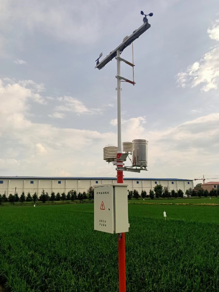
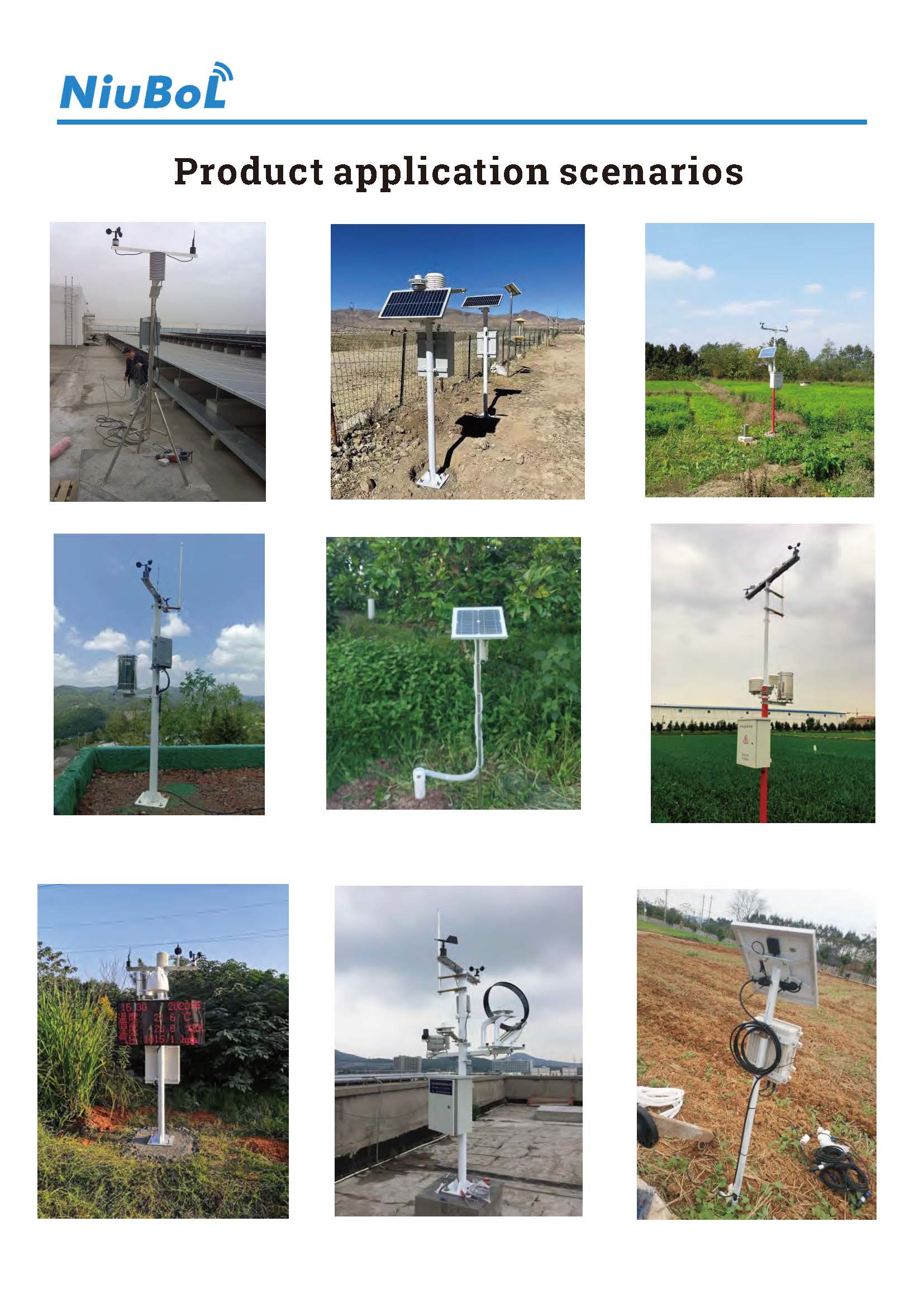
Agricultural meteorological monitoring instruments may include wind sensors, an air temperature and humidity unit, a rain gauge and optional soil or radiation channels. They can share a mast and still need different supply and signal arrangements. A purchase description that says only "12 V weather station" leaves those differences unresolved.
For an integrator, the first task is to identify the version of each instrument. Record its model, input voltage, output type and connection drawing. A replacement with the same enclosure may have a different output. Do not connect it by appearance or by the wire colors of an earlier order.
A 0-5 V output describes the measurement signal delivered to a compatible input. It does not establish the voltage that powers the transmitter. Likewise, an RS485 label identifies an electrical communication interface, not a power source, and Modbus RTU does not define a common supply voltage for every connected instrument.
Read these requirements independently. An analog input must support the selected voltage or current range. A serial input needs the correct communication settings and decoding. Both arrangements still require the sensor to receive power within the limits of its ordered version.
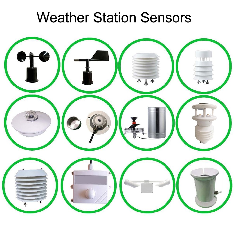
| Component | Supply or interface specification | What to settle in the order |
|---|---|---|
| NBL-W-LBTH | DC 12-24 V; RS485 Modbus RTU or 4-20 mA versions | Specify the output and matching acquisition input |
| NBL-W-SS | DC 5 V or DC 12-24 V depending on output configuration; IP65 | Identify the supply version rather than assuming all wind sensors are interchangeable |
| NBL-W-RS | DC 5 V or DC 12-24 V options; reed-switch, voltage or RS485 outputs | Distinguish the contact arrangement from powered electronic output versions |
| TG462 / TG462S | Input DC 5-35 V; peripheral outputs include 12 V, 9 V and 5 V channels | Verify the selected output rail, current allowance and complete connected load |
| TG462 / TG462S enclosure | IP30 | Install the logger inside suitable outdoor protection; sensor IP ratings do not cover it |
For a reed-switch rain gauge, follow the specified contact-input arrangement. A passive switching contact must not be treated as a voltage transmitter. Its receiving input may need a defined sensing circuit; use the approved connection drawing rather than applying a transmitter supply to an unspecified pair of wires.
Select a rail only after confirming terminal assignments and current ratings for the actual equipment supplied. The wind sensor's IP65 protection also does not define the electrical rating of an external connector or cable joint.
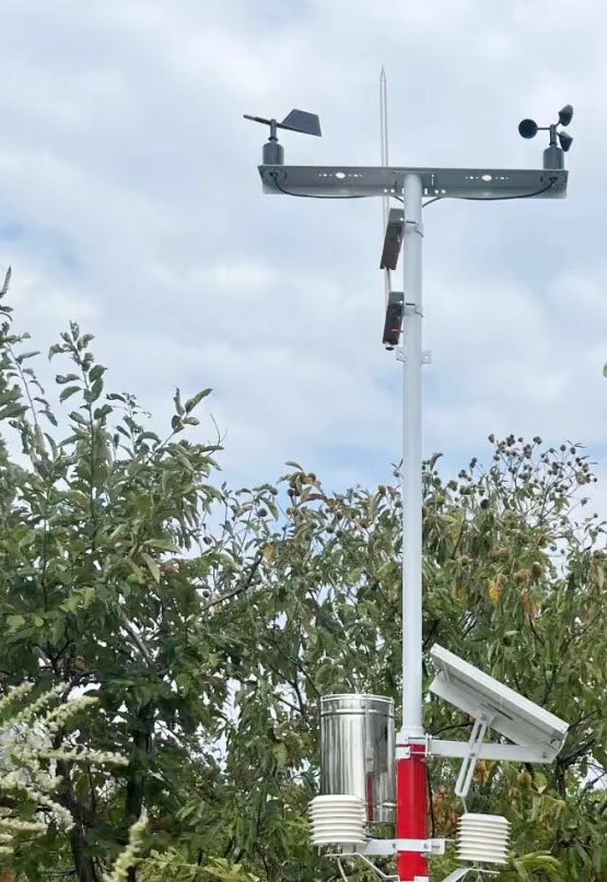
For the TG462 series, data-acquisition current is approximately 251-357 mA at 12 V, while communication current is approximately 305-412 mA at 12 V. The standard power specification is DC 12 V / 1.5 A. These figures describe different things: operating current is a load estimate, while an adapter rating describes its stated supply capacity.
As a calculation example, 12 V multiplied by 0.412 A is about 4.94 W for the logger at that stated communication current. This is not the whole station load or a guaranteed worst-case value. Connected sensors, conversion losses and any other powered equipment must be considered separately. It also does not establish the spare current available from an individual sensor-power terminal.
If a 24 V instrument is added to an otherwise 12 V installation, identify how its required voltage will be provided. If conversion is needed, include its rating and losses in the design. A battery's nominal voltage does not guarantee that every connected device remains within its input range throughout the intended operating conditions.
A supply that is correct at the cabinet can still be inadequate at the sensor because of cable and connection losses. Review conductor size, cable length and the combined current on shared conductors. Check the condition at the installed instrument under the operating states that matter, including communication activity and any switched loads.
Do not use a wider sensor measurement range as evidence of wider voltage tolerance. Wind speed range, air temperature range and power input range are separate specifications. Before changing wiring or instruments, isolate the circuit and have the connection checked by personnel responsible for the electrical installation.
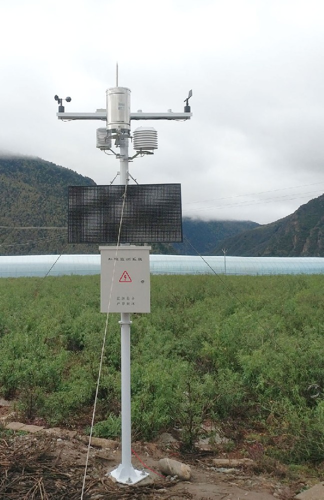
Include a power-and-signal schedule with the enquiry: one row per instrument showing supply version, output, cable length and receiver input. Identify what will be powered from the logger and what will use a separate supply. For existing stations, include current equipment labels and drawings rather than only the original station name.
At acceptance, verify the delivered versions against that schedule. Demonstrate valid acquisition with the full intended load connected, not only one sensor on a short bench cable. If a rain counter resets, a serial channel drops out or a value changes when communications starts, investigate the power and connection arrangement before adjusting the sensor's calibration.
For solar stations, use this component schedule as an input to battery and panel sizing. Choosing a panel first and trying to fit unspecified instruments afterward reverses the engineering sequence. NiuBoL can review the proposed sensor and logger combination once the required channels and destination-site conditions are identified.
No. The output range and supply specification are independent. Confirm the exact transmitter version and the available current before selecting the rail.
No. RS485 does not prescribe sensor supply voltage. Check the input requirement of every device, even when all devices share one Modbus RTU bus.
No. The logger consumes power itself, and peripheral terminals have their own limits. Check each output and the combined system load separately.
Only after confirming supply, pin assignment, output and receiver compatibility. Matching the model family or cable appearance is not sufficient.
Provide sensor versions, cable lengths, logger and network equipment, available power and required operation during supply interruptions. Separate component compatibility from the later battery-autonomy calculation.
Agricultural weather sensor power supply starts with the delivered instrument version. Keep supply ratings, measurement outputs and logger terminal limits separate, then verify operation with the intended cables and connected load. That gives the power-system design a defined electrical basis.
Prev:Farm Weather Station Automation: Observation, Advisory or Equipment Control?
Next:Small Weather Station Display Options: On-Site Readout or Remote Access?
Related recommendations
Sensors & Weather Stations Catalog
 Agriculture Sensors and Weather Stations Catalog-NiuBoL.pdf
Weather Stations Catalog-NiuBoL.pdf
Agriculture Sensors Catalog-NiuBoL.pdf
Water Quality Sensor Catalog-NiuBoL.pdf
Related products
 Combined air temperature and relative humidity sensor
 TDR Soil Moisture & Temperature Sensor for irrigation| RS485 |4-20mA| NBL-S-THR
 Soil pH sensor RS485 soil Testing instrument soil ph meter for agriculture |NBL-S-PH
 Wind Speed sensor Output Modbus/RS485/Analog/0-5V/4-20mA
 Tipping bucket rain gauge for weather monitoring auto rainfall sensor RS485/Outdoor/stainless steel
 Pyranometer Solar Radiation Sensor 4-20mA/RS485


Screenshot, WhatsApp to identify the QR code
WhatsApp number:+8615367865107
(Click on WhatsApp to copy and add friends)

