





— Blogs —
—Products—
 Consumer hotline +8618073152920
WhatsApp:+8615367865107
Address:Room 102, District D, Houhu Industrial Park, Yuelu District, Changsha City, Hunan Province, China
Product knowledge
Time:2026-01-19 16:49:13 Popularity:727
The liquid pressure sensor working principle is a conversion chain: liquid pressure loads a sensing structure, that structure changes an electrical property, and the transmitter conditions the response into a usable signal. In a piezoresistive instrument, stress changes the resistance of the sensing element. The receiving controller sees a calibrated pressure or derived quantity, not the diaphragm movement itself.
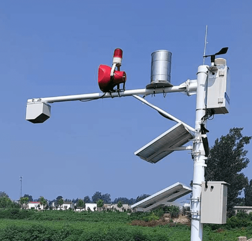
Pressure is force per unit area. A diaphragm exposed to a pressure difference deforms slightly, loading the sensing element. In a diffused-silicon piezoresistive design, the resulting resistance changes can be measured through a bridge circuit. Signal-conditioning electronics amplify and correct the small electrical response.
Some pressure assemblies isolate the sensing chip from the process through a metal diaphragm and fill fluid; others use different sensing structures. Do not infer the entire internal construction from the housing material. The isolation arrangement, seals and pressure port all matter when checking compatibility with a liquid.
The transmitter maps the conditioned response to an output such as 4–20 mA or a digital value. A sensing chip, a complete pressure transmitter and a level-monitoring station are different parts of that chain. A built-in microprocessor does not establish that every model includes a display, radio, storage or all industrial output options.
| Reference type | Quantity measured | Engineering consequence |
|---|---|---|
| Gauge pressure | Pressure relative to the instrument's atmospheric reference. | The reference must remain appropriate to the installation. |
| Absolute pressure | Pressure relative to a vacuum reference. | Includes the atmospheric contribution when observing an open liquid system. |
| Differential pressure | Difference between two pressure connections or references. | Both sides and connecting arrangements affect the result. |
These are reference definitions, not interchangeable software labels. For an open water tank, a suitable vented hydrostatic probe uses the atmosphere as its reference. For a sealed vessel, gas pressure above the liquid must be considered separately if the goal is liquid height.
Do not zero a pressurised process merely because the desired display is zero. A zero operation performed under load can remove a real pressure contribution from the indication. Establish the required reference condition and follow the selected transmitter's supported procedure.
A radar level instrument observes an electromagnetic return from the surface. It does not sense force on a wetted diaphragm. It can be useful when the objective is level and immersion is undesirable, but it cannot be substituted for a pipeline pressure transmitter merely because both results are used by the same controller.
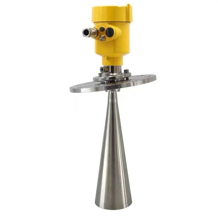
The application decides which physical variable is needed. Pump control may require pressure at a pipe connection, tank inventory may require level, and an open channel may require stage and flow. Using a level-derived signal where process pressure is required can conceal the condition the system is meant to monitor.
Similarly, neither pressure nor radar level alone identifies liquid flow. Pressure differences can be used in a suitably designed flow-measurement arrangement, but a single pressure value does not establish flow without the relevant geometry, properties and validated relationship.
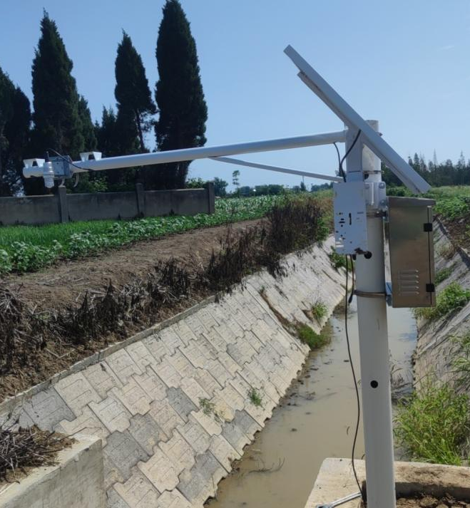
A hydrostatic relationship assumes the relevant pressure is produced by a liquid column. Local jets, pump suction and flow against an inlet can add disturbance. A pipeline transmitter may also experience rapid transients during valve or pump operation. The expected steady value is therefore not the only pressure condition to specify.
Distinguish measuring span, allowable overload and damage limits for the selected model. A higher overload rating does not mean readings remain within normal accuracy beyond the measuring span. Nor does a slow reporting interval protect the diaphragm from a fast pressure event.
If a damping arrangement is required, assess its effect on response. Restricting pressure transmission can reduce rapid fluctuations at the sensor, but it may also delay a real event and can be affected by blockage. Do not assume a special water-hammer protection device is included without a defined configuration.
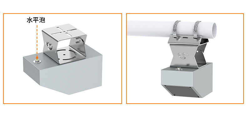
The NiuBoL NBL-L-WLPS RS485 configuration applies pressure sensing to liquid head. It is not a generic high-pressure pipeline transmitter. Its selected pressure span corresponds to the ordered water-head range, and its vented cable preserves the atmospheric reference.
| NBL-L-WLPS item | Configuration information |
|---|---|
| Measuring principle | Diffused-silicon piezoresistive hydrostatic sensing. |
| Range and accuracy | Order the required head range; 0.5%FS standard, 0.2%FS configuration available. |
| Supply and consumption | DC 10–30 V, typical 24 V; maximum 0.2 W. |
| Output | RS485 using Modbus RTU. |
| Protection and size | IP68 probe; 26.8 mm outside diameter. |
| Temperature | Circuit -20 to 80°C; liquid at or below 60°C for long-term measurement. |
| Wetted assembly | Stainless-steel probe and vented cable; confirm exact materials and cable jacket for the liquid. |
For liquid level, pressure must be converted using density and gravity. With an assumed water density of 1000 kg/m³ and g = 9.81 m/s², a pressure difference of 9.81 kPa corresponds to 1 m of head. It is a conversion example, not evidence that any pressure sensor has a 1 m span or that the same density applies to other liquids.
In a water-supply network, a suitable pipe-mounted transmitter can provide pressure feedback for pump control. Its connection, span and transient tolerance must match that service. The controller and drive determine the control response; the sensor alone does not guarantee constant delivery pressure.
In irrigation, readings taken under comparable operating conditions can help investigate filter or distribution problems. A suspected filter restriction is better assessed using the relevant upstream and downstream conditions than by treating any single pressure drop as proof of blockage. Valve states and active irrigation zones also affect pressure.
In a tank or reservoir, a hydrostatic probe provides head above its diaphragm. It does not directly measure contamination, flow or total stored volume. Those applications need their own measurements or conversion information. Keeping the quantity explicit prevents a pressure signal from being given more diagnostic meaning than it supports.
When a reading is wrong, compare the physical reference, local raw output and receiver conversion before adjusting the transmitter. For a 4–20 mA model, check loop supply and input scaling. For an RS485 model, check supply, serial settings, device address, register interpretation and data freshness.
Digital communication is not immune to cable loss or installation problems. Voltage drop still affects power, while topology, electrical noise and termination can affect communication. A failed request is not always caused by a missing resistor, and a fixed cable-distance claim cannot replace a bus design.
For a pressure enquiry, provide the normal, maximum and transient conditions; the liquid composition and temperature; the required reference type; and the connection and receiver details. For a hydrostatic application, add probe position, head range and cable route. These distinguish the instrument required more usefully than asking for one broad pressure range and every possible output.
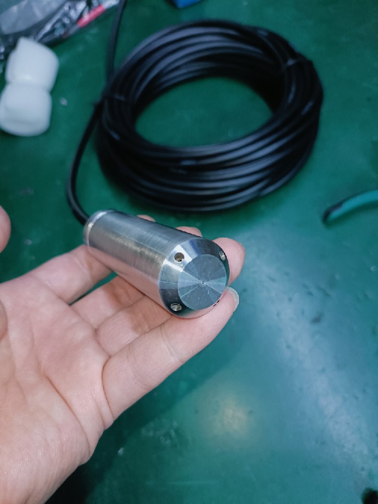
Stress changes the sensing element's resistance. A bridge circuit detects the change, and conditioning electronics convert the response into the calibrated output. The complete transmitter design determines its range and interface.
Not when pressure itself is required. Radar measures surface distance. It may be an alternative for a level task, but it does not provide the same process-pressure information at a pipe connection.
No. Compatibility depends on the exact liquid, concentration, temperature and every wetted material, including seals and cable where present. Obtain a material assessment for the actual service rather than relying on the housing description.
No. Overload tolerance and measurement span are different limits. Check accuracy within the ordered span and use the specified overload and damage limits when assessing abnormal events.
No. Averaging changes reported data, not the pressure loading at the diaphragm. Assess the physical transient and any suitable pressure-protection arrangement separately from display filtering.
The controller may use an incorrect density, pressure reference, decimal scaling or installation offset. Verify what the raw value represents and compare it with a suitable reference before changing calibration.
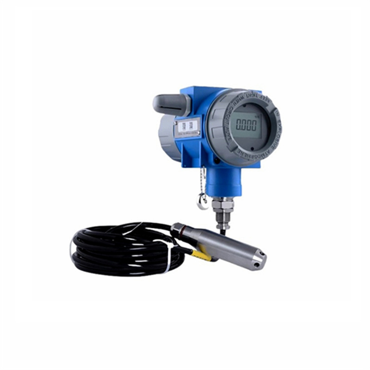
A liquid pressure sensor converts a pressure difference into an electrical result through its sensing structure and conditioning electronics. Useful integration requires the right pressure reference, wetted assembly and receiver interpretation. For NiuBoL hydrostatic monitoring, specify those conditions as a defined level application rather than applying generic pipeline-pressure claims to an immersed probe.
Prev:Water Level Sensor Principles: Signals and Measurement Limits
Next:Liquid Level Sensor vs Water Level Sensor: Media and Model Limits
Related recommendations
Sensors & Weather Stations Catalog
 Agriculture Sensors and Weather Stations Catalog-NiuBoL.pdf
Weather Stations Catalog-NiuBoL.pdf
Agriculture Sensors Catalog-NiuBoL.pdf
Water Quality Sensor Catalog-NiuBoL.pdf
Related products
 Combined air temperature and relative humidity sensor
 TDR Soil Moisture & Temperature Sensor for irrigation| RS485 |4-20mA| NBL-S-THR
 Soil pH sensor RS485 soil Testing instrument soil ph meter for agriculture |NBL-S-PH
 Wind Speed sensor Output Modbus/RS485/Analog/0-5V/4-20mA
 Tipping bucket rain gauge for weather monitoring auto rainfall sensor RS485/Outdoor/stainless steel
 Pyranometer Solar Radiation Sensor 4-20mA/RS485


Screenshot, WhatsApp to identify the QR code
WhatsApp number:+8615367865107
(Click on WhatsApp to copy and add friends)

