





— Blogs —
—Products—
 Consumer hotline +8618073152920
WhatsApp:+8615367865107
Address:Room 102, District D, Houhu Industrial Park, Yuelu District, Changsha City, Hunan Province, China
Product knowledge
Time:2024-11-20 14:08:29 Popularity:5331
Water level sensors work by detecting a physical quantity related to the liquid surface: pressure, echo distance, float position or a change at a probe. Continuous sensors provide a changing level or distance value; point switches indicate whether liquid has reached a particular position. The measurement principle determines the installation, conversion and likely failure modes. A NiuBoL level instrument should therefore be selected by its actual method and output, not by a generic water-sensor label.
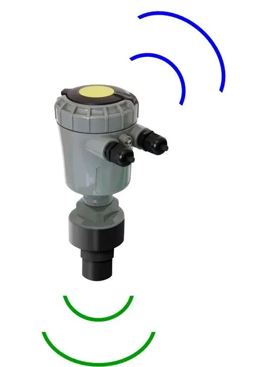
An above-water ultrasonic sensor sends a sound pulse towards the surface and detects the returning echo. Distance is calculated from sound velocity multiplied by round-trip travel time, divided by two. A level value then requires an installation reference. The transmitter must distinguish the water echo from reflections caused by walls, pipes or other objects.
Sound propagation depends on conditions along the acoustic path. Temperature variation, foam, condensation and obstructions can matter even though the sensor does not touch the water. Confirm the instrument's blind zone, echo geometry and actual specification; a universal +/-0.2 mm accuracy cannot be assigned to ultrasonic water level sensors as a category.
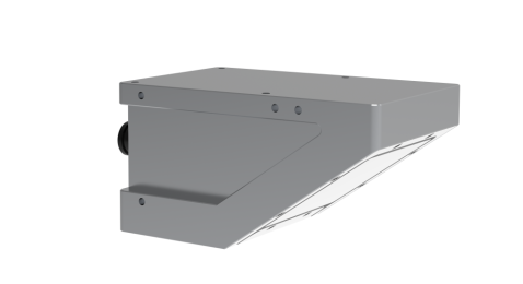
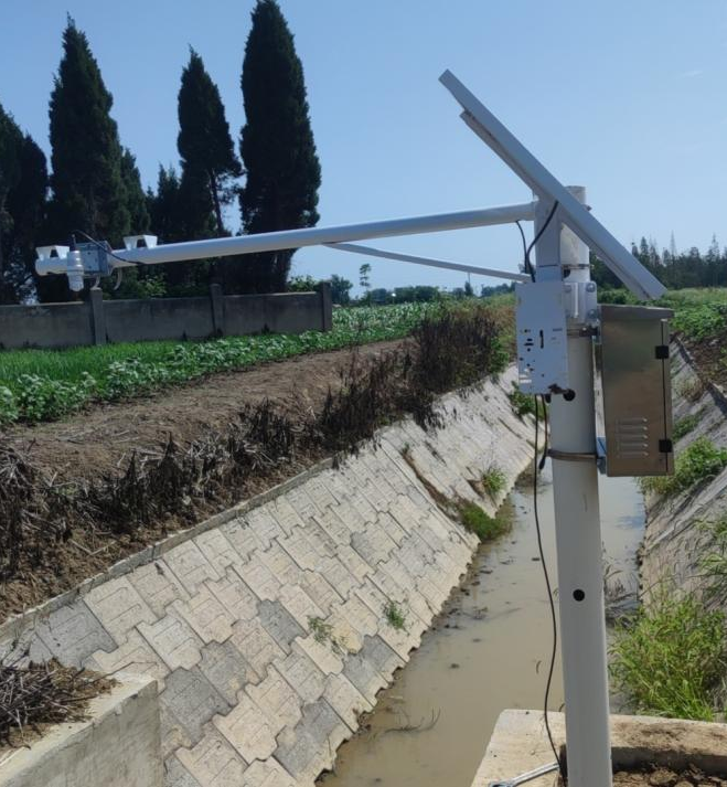
A radar level sensor transmits electromagnetic energy towards the liquid and receives a reflection. In the NiuBoL FMCW arrangement, the transmitted frequency varies and the electronics use the difference between the transmitted and received signals to calculate distance. This is not an acoustic measurement and does not use the speed of sound in air.
The 77-79 GHz radar water level sensor measures a surface range. A radar flowmeter can additionally have a velocity channel and a flow calculation, but those are separate functions. Level alone does not establish discharge without an appropriate site relationship or additional measurement arrangement.
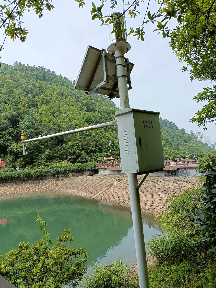
For a fixed overhead sensor, a rising surface normally produces a shorter sensor-to-water distance. Converting that distance to level requires the height of the sensor reference above the chosen zero. As an illustrative calculation, a reference height of 6.0 m and a distance of 2.4 m give a level of 3.6 m above that zero. This is not automatically the total water depth.
A water-surface elevation also requires an elevation datum; water depth requires a defined bottom reference. Keep the reference and sign convention with the value. The USGS report on stage measurement describes float, pressure and non-contact methods for observing water levels.
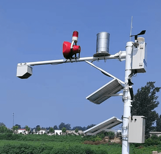
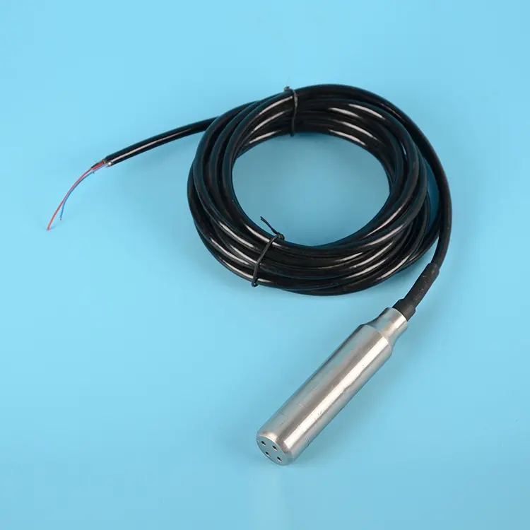
A submerged hydrostatic probe senses pressure from the overlying liquid. In a simple static relationship, h = P/(rho x g), where P is the liquid-column pressure after the appropriate pressure-reference treatment, rho is liquid density and g is gravitational acceleration. The result is height above the pressure-sensing point, not the distance down from a bridge.
The NiuBoL submersible level transmitter uses a diffused-silicon pressure element and a vented cable arrangement. The vent provides an atmospheric reference; it must remain dry and unobstructed. Density changes, a displaced probe or a damaged vent path can change the interpretation even when the electrical connection remains intact.
| Specification | Radar level configuration | Submersible pressure configuration |
|---|---|---|
| Principle | 77-79 GHz FMCW distance measurement | Hydrostatic pressure |
| Range | 0.1-65 m standard | 5 m standard; other ranges selected separately |
| Accuracy specification | +/-1 mm under specified conditions | 0.2% FS or 0.5% FS, depending on configuration |
| Supply | DC 10-30 V | DC 10-30 V |
| Output | RS485 Modbus RTU | RS485 Modbus RTU for this configuration |
| Power | Less than 0.2 W | Static consumption no more than 0.2 W |
| Protection | IP67 | IP68 probe |
| Temperature conditions | Operating: -40 to 60 C | Operating: -40 to 80 C; recommended medium temperature no more than 60 C for long-term measurement |
Full-scale percentage and millimetre specifications are not interchangeable. For the 5 m pressure range, 0.2% FS corresponds to 10 mm and 0.5% FS to 25 mm. Those calculations explain the specified terms; they are not a complete uncertainty statement for an installed well, river or tank.
A float follows the liquid surface through buoyancy. A mechanical linkage, encoder or magnetic arrangement then converts its movement into an indication or electrical result. A float switch can indicate one operating position, while an appropriate position-measuring assembly can provide continuous level. The required liquid density and freedom of movement matter.
In a magnetic level indicator, a float can operate an external indication through a chamber wall. In a magnetostrictive instrument, a magnetic float's position along the probe is detected by a different sensing arrangement. External electronics or magnetic coupling do not make the float and chamber non-contact with the process liquid. Deposits, a blocked chamber connection or restricted float travel remain relevant.

A capacitive level instrument responds to a change in electrical capacitance as the material around its probe changes. Some designs provide a point indication; others infer continuous level along a measuring length. Liquid dielectric properties, coating and the installation arrangement affect suitability. One calibration cannot be assumed appropriate for every liquid.
A conductive probe detects the electrical path formed when a sufficiently conductive liquid contacts the electrodes. It is generally used for point detection rather than an arbitrary continuous depth value. An optical point probe can detect a change in light behaviour at a prism when liquid reaches it. That wetted optical probe is different from a remote laser distance instrument.
Choose the method for the liquid and the required result. A high-level switch, a continuously varying depth and a measured surface distance serve different tasks. Combining them can be useful, but none should be relabelled as another quantity merely to match a display field.
A 4-20 mA transmitter needs the correct level span at the analog input. An RS485 instrument needs its actual protocol, units and field mapping. A switch provides state, not a multi-point level curve. Confirm whether a PLC, RTU or data logger receives distance, level relative to a zero, or pressure that still requires conversion.
For commissioning, compare a suitable known level or distance with the local instrument and the final screen. Check whether the reading increases or decreases as expected when the surface changes. A pump, alarm or remote telemetry system is downstream of this measurement and needs its own specified logic and response checks.

Usually it first measures the distance to the surface. Total depth needs the bottom reference, while elevation needs an appropriate datum. Confirm which converted quantity the receiving system uses.
No. FMCW radar varies the transmitted frequency and uses the received signal's frequency relationship to determine range. Use the principle of the selected instrument rather than assigning one internal method to every radar.
Hydrostatic pressure depends on density as well as height. If the conversion assumes a fixed density, a change in the actual liquid can affect the calculated level. Check the medium and pressure reference rather than adjusting only the display zero.
Not simply because its readout is outside the vessel. The float and associated chamber or probe may contact the liquid. Assess wetted materials and free movement for the actual construction.
Only if the task requires the corresponding switching state rather than a continuously varying measurement. A pump high-level indication and a reservoir stage record have different data requirements.
Not by level measurement alone. Water quality needs the relevant analytical sensors. Flow requires an appropriate level-to-flow relationship or a defined combination of velocity, geometry and calculation.
Understanding how water level sensors work means identifying the sensed quantity and the conversion to the required result. Pressure, echo ranging, float position and point detection have different installation and interpretation needs. Match the NiuBoL instrument, its interface and its reference to the required continuous measurement or switching task.
Prev:Automatic Weather Station Manufacturer: Repeat Orders and Replacements
Next:Weather Station for Freezing Conditions: Check Each Channel
Related recommendations
Sensors & Weather Stations Catalog
 Agriculture Sensors and Weather Stations Catalog-NiuBoL.pdf
Weather Stations Catalog-NiuBoL.pdf
Agriculture Sensors Catalog-NiuBoL.pdf
Water Quality Sensor Catalog-NiuBoL.pdf
Related products
 Combined air temperature and relative humidity sensor
 TDR Soil Moisture & Temperature Sensor for irrigation| RS485 |4-20mA| NBL-S-THR
 Soil pH sensor RS485 soil Testing instrument soil ph meter for agriculture |NBL-S-PH
 Wind Speed sensor Output Modbus/RS485/Analog/0-5V/4-20mA
 Tipping bucket rain gauge for weather monitoring auto rainfall sensor RS485/Outdoor/stainless steel
 Pyranometer Solar Radiation Sensor 4-20mA/RS485


Screenshot, WhatsApp to identify the QR code
WhatsApp number:+8615367865107
(Click on WhatsApp to copy and add friends)

