





— Blogs —
—Products—
 Consumer hotline +8618073152920
WhatsApp:+8615367865107
Address:Room 102, District D, Houhu Industrial Park, Yuelu District, Changsha City, Hunan Province, China
Product knowledge
Time:2025-01-11 16:56:06 Popularity:2053
Nighttime visibility observations need a clear distinction between a visible light and meteorological optical range, or MOR. The distance at which a person can detect a lamp depends on the lamp, the background and the viewing conditions as well as the atmosphere. A forward-scattering sensor estimates MOR from a local optical measurement. The two observations can differ without either being a simple calibration error.
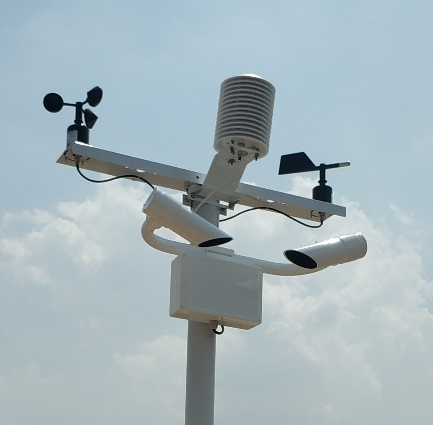
A port operator may see a bright light while a nearby sensor reports a much shorter MOR. A road observer may lose sight of a dim object before losing a brighter one at the same distance. Those comparisons involve different visual targets. Treating the farthest visible light as a direct reference for the instrument can produce a misleading fault report.
The American Meteorological Society explanation of Allard's law relates the night visual range of a light to atmospheric extinction, the source and the observer's detection threshold. This is why an arbitrary lamp is not an interchangeable reference target. Brightness, beam direction and background conditions matter.
For an instrument enquiry, first state the required quantity: MOR, a specified visual-observation report, or a separate operational quantity such as runway visual range. Do not ask a supplier to guarantee that a MOR reading always equals the distance to a particular streetlight. The light may not have a stable known intensity, and the line of sight may pass through air that differs from the sensor location.
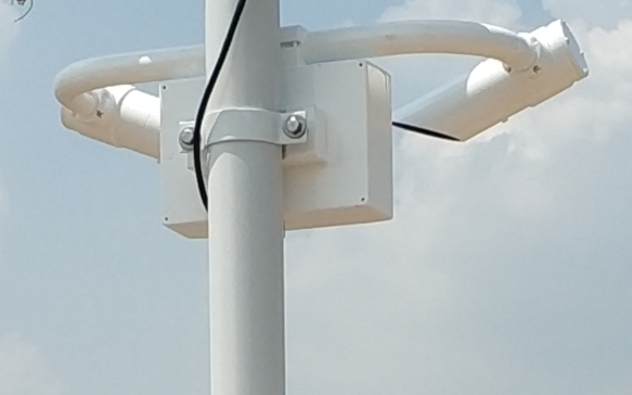
MOR is an atmospheric optical quantity rather than a measurement of human eyesight. The Met Office description of visibility measurement defines it using the path length over which luminous flux is reduced to 5% of its initial value. That definition is different from asking whether a person can still see an illuminated sign.
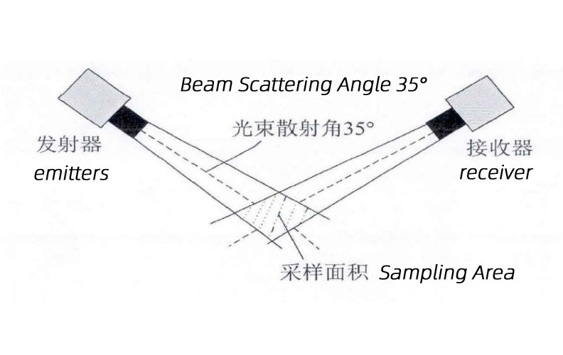
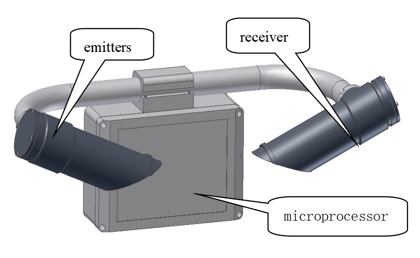
The NiuBoL NBL-W-VS uses forward scattering. Its transmitter illuminates a small atmospheric sampling zone, the receiver detects scattered light, and the processing converts that optical signal into an estimate of MOR. It does not aim at a harbour light or measure the complete road ahead of a driver.
| Observation | What affects the result | Suitable use |
|---|---|---|
| Distance to a visible light | Atmosphere, light output and direction, background and observer conditions | A structured visual observation when the method and targets are defined |
| Forward-scattering MOR | Local optical sampling, conversion method, instrument condition and representative siting | A time-stamped atmospheric visibility channel |
| Transmission-based measurement | Attenuation over the instrument's defined optical path | A different instrument method, selected for the project requirement |
| Operational viewing distance | Application-specific targets, geometry, lighting and reporting rules | A separately specified operational assessment, not an automatic relabelling of MOR |
The scattering schematic below represents a localized sampling volume. It is not an observer-to-light sightline. For a fuller comparison of instrument methods, see the forward-scattering visibility sensor guide. A method comparison and a nighttime visual comparison should not be treated as the same test.
The atmospheric NBL-W-VS configuration measures 5 m-10 km. At the upper limit, establish how the logger labels capped or out-of-range results rather than presenting the limit as an exact observation of indefinitely clear conditions. A sensor at its reporting ceiling cannot quantify how far actual visibility extends beyond that ceiling.
| Parameter | Atmospheric NBL-W-VS | Integration implication |
|---|---|---|
| Measured quantity and range | MOR; 5-10,000 m | Keep metres and kilometres distinct in displays and exports |
| Optical principle | Aerosol forward scattering | Inspect the local sampling area and optical windows |
| Peak wavelength | 875 nm | The instrument uses its own optical source, not the observed external lamp |
| Supply and average power | DC 12 V; approximately 0.8 W | Account separately for logger, gateway and other station loads |
| Interface | RS485 Modbus RTU; default 9600 bps | Verify the receiving register map, units and status interpretation |
| Environment and cable | -40 to 80 degrees C; IP65; standard 10 m cable | Keep installation and cleaning access suitable for the actual site |
A manufacturer's range and laboratory specification do not establish agreement with every observer report. Define the reference method and required comparison conditions in the project acceptance plan. For aviation, MOR and runway visual range are distinct quantities; assess the required equipment and operational requirements separately.
Make visual checks from a safe, approved location. A roadside comparison should not require a person to stand in traffic or move into an operationally restricted area. Observation records can support an investigation, but they are not permission to bypass the site's safety arrangements.
If the sensor reports 600 m MOR and an observer can see a lamp at 1 km, the statement that the sensor is 400 m low is not justified by those two facts alone. The example illustrates unlike quantities; it is not a measured result from a NiuBoL installation. Check the visual target and observation method before changing instrument settings.
Equally, do not dismiss every disagreement as an observer issue. Repeated discrepancies under comparable conditions warrant a review of contamination, siting, the receiving system and instrument performance. Store the original readings while investigating so a software correction does not conceal the evidence needed to find the cause.
Tell NiuBoL the application, required quantity and range, mounting environment, receiving PLC or RTU, reporting interval and intended reference procedure. If the system combines MOR with visual reports, use different field names and retain their observation times. An RS485 Modbus RTU connection can transfer the sensor value; it cannot make unlike observations equivalent.
For ports, roads and industrial sites, the operational response should be defined by the responsible authority or site procedure. Avoid deriving universal stopping distances, closure thresholds or navigation permissions from a single instrument specification. The useful output is a correctly labelled observation delivered to a system that understands its scope.
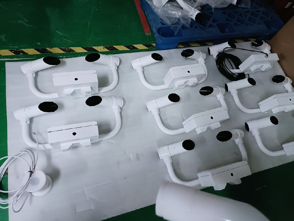
A light's visual range depends on its output and direction, the background and the observer's detection conditions as well as the atmosphere. MOR is a separate optical quantity. Visibility of an arbitrary light does not directly validate or invalidate the MOR value.
No. It uses its own optical transmitter and receiver. Day and night comparisons still need to distinguish instrument MOR from human visual observations and account for representative siting and instrument condition.
It reaches the upper end of the specified 5 m-10 km range. Check the device status and reporting convention. Do not interpret a capped value as an exact measurement of visibility beyond the sensor's range.
No. They are distinct quantities. A project requiring runway visual range needs a separate assessment of the measurement system and operational requirements; a MOR register must not simply be renamed RVR.
Retain the sensor value and status, observation time, target distance and direction, lighting conditions, local weather and optical-window condition. Establish whether the comparison uses the same quantity before requesting calibration changes.
Nighttime visibility observations become useful when the reported quantity is clear. Keep MOR separate from the visual range of a lamp, compare observations at the same time and investigate site and instrument conditions before adjusting calibration. This gives operators an interpretable record without claiming that one sensor describes every viewing condition.
NBL-W-VS visibility sensor instruction manual.

Prev:Pest Monitoring System Software Updates: Keep Insect Trends Comparable
Next:Agricultural Weather Station for Crop Emergence: Investigating Uneven Stands
Related recommendations
Sensors & Weather Stations Catalog
 Agriculture Sensors and Weather Stations Catalog-NiuBoL.pdf
Weather Stations Catalog-NiuBoL.pdf
Agriculture Sensors Catalog-NiuBoL.pdf
Water Quality Sensor Catalog-NiuBoL.pdf
Related products
 Combined air temperature and relative humidity sensor
 TDR Soil Moisture & Temperature Sensor for irrigation| RS485 |4-20mA| NBL-S-THR
 Soil pH sensor RS485 soil Testing instrument soil ph meter for agriculture |NBL-S-PH
 Wind Speed sensor Output Modbus/RS485/Analog/0-5V/4-20mA
 Tipping bucket rain gauge for weather monitoring auto rainfall sensor RS485/Outdoor/stainless steel
 Pyranometer Solar Radiation Sensor 4-20mA/RS485


Screenshot, WhatsApp to identify the QR code
WhatsApp number:+8615367865107
(Click on WhatsApp to copy and add friends)

