





— Blogs —
—Products—
 Consumer hotline +8618073152920
WhatsApp:+8615367865107
Address:Room 102, District D, Houhu Industrial Park, Yuelu District, Changsha City, Hunan Province, China
Product knowledge
Time:2026-02-23 10:07:55 Popularity:724
Flow and water quality sensor integration should make measurements comparable, not merely place them on one screen. A Doppler meter, an oxygen probe and a pumped water sample can observe different water at different times. Define the measurement location, acquisition time and validity of each channel before interpreting their trends together.
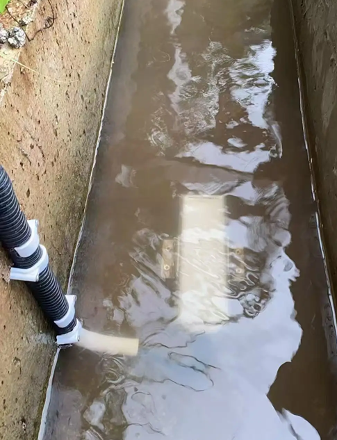
A channel operator may need to know whether an oxygen change accompanies a flow reduction, whether a turbidity event occurs during a rising river, or whether a nitrogen trend follows a process discharge. Each question requires a particular combination of measurements. Installing every available probe can increase maintenance without resolving the actual uncertainty.
Identify which quantity is measured directly and which is calculated. A Doppler instrument measures velocity and pressure-related level; section discharge also depends on geometry and a representative velocity relationship. A water-quality probe measures its defined chemical or optical response. Sharing a logger does not make those measurements spatially representative of the same river section.
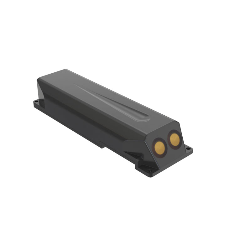
The NiuBoL Doppler velocity meter is a submerged contact instrument. It needs suitable water coverage and acoustic returns from moving particles or bubbles. Very clear water can provide weak returns; deposits and heavy aeration can also cause problems. Low sediment content alone is not sufficient evidence of suitability.
Check minimum water level, the sensor's physical elevation, flow direction and the possibility of burial. The lower end of a depth measurement range is not an installation instruction stating that a few centimetres of water above the channel bed will always cover the complete sensor correctly.
| Device or channel | Relevant configuration parameters | Integration consequence |
|---|---|---|
| Doppler meter | Standard velocity 0.03-5 m/s, unidirectional; depth 0.03-5 m | Assess immersion and specify reversal capability separately if needed |
| Doppler power and interface | DC 10-30 V; 65 mA standby and 106 mA measurement at 12 V; RS485 Modbus RTU | Keep acquisition and power sizing specific to this device |
| NBL-WQ-DO oxygen probe | 0-20.00 mg/L; accuracy ±2% F.S.; resolution 0.01 mg/L | Record concentration separately from percent saturation |
| NBL-WQ-DO operating conditions | 0-50 C; pressure below 0.2 MPa; 12-24 VDC; 0.2 W at 12 V | Do not transfer another probe version's limits to this configuration |
| Ammonium probe options | NBL-WQ-NHN ranges 0-10, 0-100 or 0-1000 mg/L | Select the intended range and confirm the nitrogen reporting basis |
| Cables and wet-end protection | DO and NHN standard cable length 5 m; IP68 probe configurations | Confirm cable jacket compatibility and waterproof terminations separately |
These are individual instrument parameters, not a uniform station specification. Mounting, water conditions and comparison checks determine whether the combined record is useful. Do not describe the entire cabinet, power system or gateway as IP68 because selected probes have that rating.
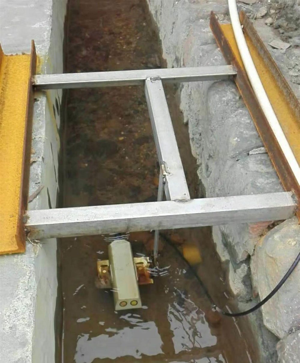
A sheltered pocket convenient for probe retrieval may not represent water passing the flow section. Conversely, installing an oxygen probe in an aerated jet can make it unsuitable for observing the broader channel condition. Select a measurement depth and position that answer the intended water-quality question through the operating level range.
Where the quality probe and flow meter cannot share a suitable section, document their separation and intervening inflows. Do not impose a universal one-metre spacing. The important questions are whether brackets or sampling hardware disturb the measurement and whether the two instruments observe comparable water.
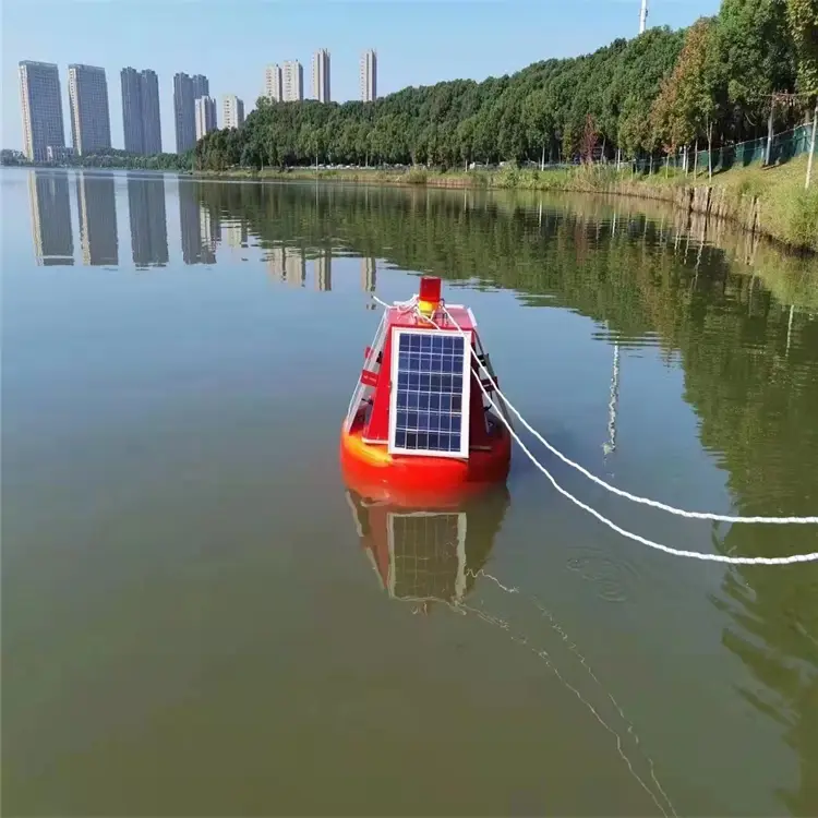
A buoy offers another deployment arrangement for water-quality observation. Its mooring, changing immersion and service access require their own design. A buoy oxygen record should not automatically be treated as the concentration at a bank-mounted discharge section simply because both records appear under the same station name.
A logger can poll several probes in one scan, but that does not establish identical measurement response. A filtered flow output, an optical oxygen response and a sample pumped to a cabinet can each describe a different effective time window. Record the relevant acquisition and averaging definitions.
For a pumped sample, estimate transport delay before comparing an event with direct immersion measurements. As an illustrative hydraulic calculation, a 2 L sample path at a steady 60 L/h gives approximately two minutes of nominal transit time. Mixing, instrument response and variations in actual flow add uncertainty; this arithmetic is not a validated correction for every sample line.
Use acquisition time rather than server arrival time for trend comparisons. A communications backlog can deliver old records beside current values. Mark delayed and invalid observations so an upload event is not mistaken for a sudden water-quality event.
The NiuBoL fluorescence dissolved oxygen probe contributes an oxygen concentration channel and associated temperature information. A changing oxygen value can justify investigation, but it does not directly identify a pollutant or measure laboratory BOD.
Keep compensation settings traceable when interpreting concentration and saturation. Compare the same quantity with a suitable reference. If a cap is cleaned or replaced, identify that service interval; a step in the trend may reflect maintenance rather than a changed river condition.
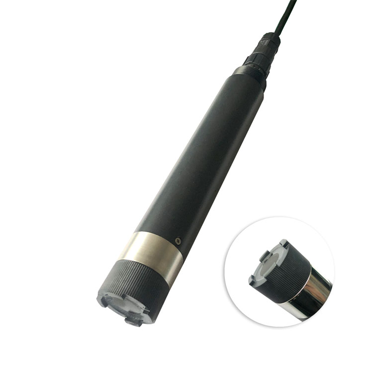
The NiuBoL ammonium ion-selective probe requires assessment of the water matrix and relevant interfering ions. Confirm how its output is expressed before comparing it with laboratory nitrogen results. Ammonium, ammonia-related reporting and total nitrogen are not interchangeable labels.
A pH or temperature change can affect the interpretation of nitrogen-related observations. Keep supporting values and the reference sampling time rather than trying to explain every concentration change from discharge alone. Paired sample comparisons over representative water conditions are more useful than one successful check in a clean standard.
For every tag, identify the instrument, unit, quantity, location and quality state. Keep flow in m3/s distinct from accumulated volume in m3, oxygen in mg/L distinct from saturation, and turbidity distinct from optical transparency. Similar-looking numeric trends do not establish the same physical meaning.
Connect compatible devices to the PLC, RTU or data logger using their actual register definitions. Unique RS485 addresses and matching serial settings establish part of the bus configuration; correct scaling and channel identity still need an end-to-end check. Do not assume that the gateway supplies an unspecified cloud service or reference analysis.
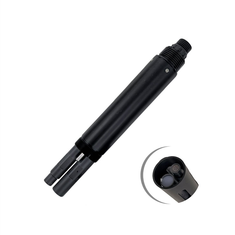
An optical transparency probe measures a transmission-related property over its optical path. It is not a universal substitute for a required turbidity method or suspended-solids measurement. Keep its result labelled correctly and assess whether colour, fouling or placement could explain changes.
A residual chlorine probe belongs to a defined disinfected-water or treatment investigation, not automatically to every river station. If the project needs a controlled sample cell, allow for its flow, pressure and delay. Do not combine its installation requirements with an immersion assembly simply because the electrical interface is compatible.
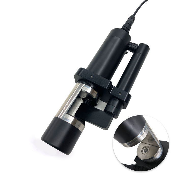
Check the hydraulic channel against its agreed comparison and each analytical channel against its appropriate reference. Then follow a time-stamped test sequence through the logger and destination. Confirm which records are observed, averaged, delayed or unavailable and how maintenance periods are marked.
Inspect whether a single disconnected probe affects the remaining bus and whether the receiver preserves unaffected channels correctly. A valid flow record does not make a failed chemical channel valid. Keep each channel's status rather than assigning one undifferentiated good/bad flag to the whole station.
Send NiuBoL the section drawing, expected water levels and velocity, analytical targets, probe positions and destination requirements. Identify any sample pump or special cell. These details determine the acquisition, mounting and power scope more reliably than a generic request for a combined river monitoring package.
Not automatically. They can have different acquisition, filtering and response times. Establish timestamps and effective intervals at the logger before interpreting short events across channels.
No. Doppler needs adequate acoustic returns and suitable immersion. Test the actual clear-water, low-flow and higher-solids conditions rather than selecting it from sediment description alone.
They need representative water and must not disturb each other's measurement. Co-location may help, but unsuitable hydraulics or service access can justify separate positions with their relationship documented.
No. Oxygen, optical scattering, transparency and ion-selective responses represent different quantities. Use the actual analytical basis and supporting reference checks before assigning environmental meaning.
No. Include all probes, logger, modem and any pump or cleaner in the load calculation. Local charging conditions and usable battery capacity determine autonomy; an acquisition interval alone does not establish it.
Show independently checked channels, positions, time definitions and correct destination labels. Include a delayed sample or communications record and an invalid probe state so their treatment is demonstrated rather than assumed.
Flow and water quality sensor integration is useful when the measurements share an understood relationship in location, time and analytical meaning. Check the Doppler installation, validate each selected probe and preserve channel-level quality at the receiver. This supports a defensible event investigation without claiming that a shared logger makes every observation equivalent.
Prev:Ecological Flow Monitoring Points: Release Outlet or Downstream Reach?
Next:Multi-Parameter Water Quality Analyzer: Industrial-Grade Water Quality Monitoring Solution
Related recommendations
Sensors & Weather Stations Catalog
 Agriculture Sensors and Weather Stations Catalog-NiuBoL.pdf
Weather Stations Catalog-NiuBoL.pdf
Agriculture Sensors Catalog-NiuBoL.pdf
Water Quality Sensor Catalog-NiuBoL.pdf
Related products
 Combined air temperature and relative humidity sensor
 TDR Soil Moisture & Temperature Sensor for irrigation| RS485 |4-20mA| NBL-S-THR
 Soil pH sensor RS485 soil Testing instrument soil ph meter for agriculture |NBL-S-PH
 Wind Speed sensor Output Modbus/RS485/Analog/0-5V/4-20mA
 Tipping bucket rain gauge for weather monitoring auto rainfall sensor RS485/Outdoor/stainless steel
 Pyranometer Solar Radiation Sensor 4-20mA/RS485


Screenshot, WhatsApp to identify the QR code
WhatsApp number:+8615367865107
(Click on WhatsApp to copy and add friends)

