





— Blogs —
—Products—
 Consumer hotline +8618073152920
WhatsApp:+8615367865107
Address:Room 102, District D, Houhu Industrial Park, Yuelu District, Changsha City, Hunan Province, China
Product knowledge
Time:2025-04-09 11:24:18 Popularity:1361
PV weather station alarms should distinguish a changing environmental condition from an unreliable measurement and from a confirmed plant fault. Low irradiance, an elevated module-temperature reading and a wind channel that stops updating call for different checks. Use the NiuBoL station's defined channels with timestamps and validity checks, then compare relevant plant information before deciding what action is justified.

A message such as solar plant abnormal is difficult to investigate. It does not tell the operator whether sunlight has fallen, one sensor has stopped updating or an inverter has limited output. Separate messages for low irradiance, stale irradiance data and plant electrical events give the responsible team a more useful starting point.
The weather station measures environmental conditions. Plant electrical faults require the relevant electrical observations or equipment status, which are not automatically included in a weather-sensor package. Likewise, a local weather observation is not a forecast of a storm that has not yet arrived. The alarm system should describe the measured condition without assigning an unsupported cause.
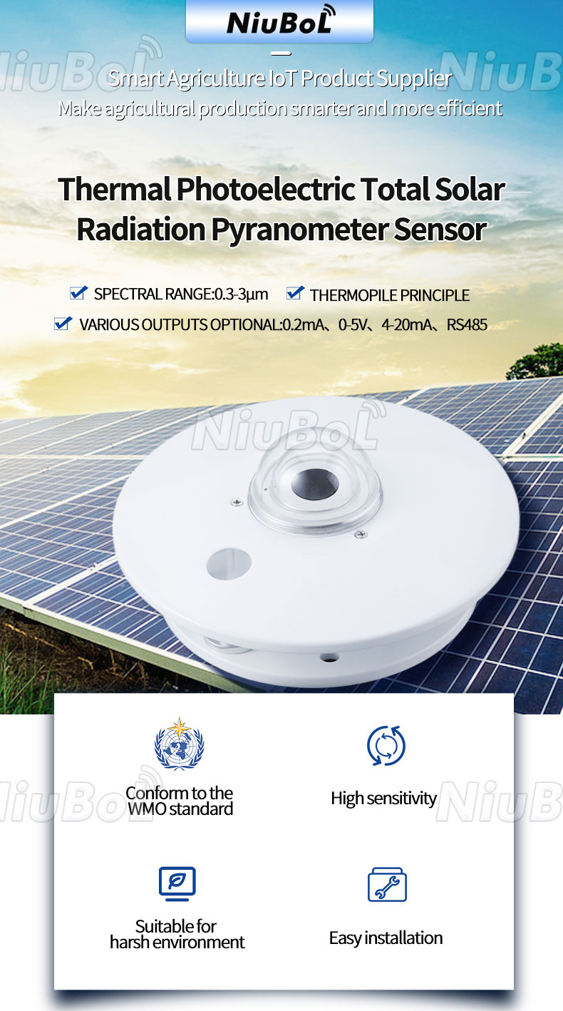
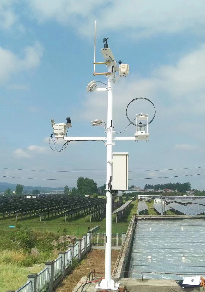
The NBL-W-HPRS pyranometer measures solar irradiance at its installed plane. A daytime fall can reflect changing sky conditions, local shading or an optical-surface problem. Inspect the timestamp and status before treating the number as current. Compare a second suitable reference or site conditions when available, while recognizing that different measurement planes need not have identical values.
If the pyranometer is shaded by a mast or fouled while the array remains exposed, the weather record can understate available irradiance. If its reading is frozen at an earlier bright-sky value, it can overstate current irradiance. Both conditions can distort an investigation of plant output, but neither is established by an electrical power drop alone.
The HPRS response time is up to 35 seconds to 99%. Polling its digital interface more frequently does not make its physical response instantaneous. Include the sensor response, acquisition period and any filtering when setting an alert delay. An arbitrary fast alarm can otherwise react to a comparison between differently timed channels.
A pyranometer does not measure atmospheric temperature and humidity. Those quantities require an air sensor such as NBL-W-LBTH. The NBL-W-PPT measures a local module back-surface temperature with a contact probe. The air channel and module channel serve different purposes and should have distinct labels and decision rules.
| Instrument | Relevant specification | Meaning for an alarm |
|---|---|---|
| NBL-W-HPRS pyranometer | 0-2000 W/m²; 0.3-3 µm; response ≤35 s to 99% | Local irradiance in a defined plane, not ambient temperature or a direct electrical-fault diagnosis |
| NBL-W-PPT module-temperature probe | Standard -50°C to 100°C; ±0.5°C; DC 5/12/24 V options; RS485 or selected analog output | Temperature at the bonded back-surface point, not a thermal image of the entire array |
| NBL-W-LBTH air sensor | Air temperature -40°C to 80°C, ±0.5°C; humidity 0-100%RH, ±5%RH; DC 12-24 V | Ambient conditions at the shielded sensing location, separate from module temperature |
| Digital acquisition | RS485 Modbus RTU for the specified digital LBTH and PPT versions | Verify unit, channel identity and freshness before evaluating a limit. |
A single bonded temperature point cannot locate every cell-level hot spot or replace a thermal survey. An unusual local value may justify inspection, but it is not proof of a fire hazard or a particular component failure. Select any operational temperature limit using the relevant equipment requirements and project procedure, not a universal weather-station threshold.
If the contact probe loosens, its thermal relationship to the back surface changes. Inspect the attachment, cable strain and surface contact when its trend becomes inconsistent with its previous behavior. Do not immediately apply a correction coefficient to make it resemble another point. The discrepancy may be mechanical rather than a genuine module-temperature change.
Compare the relevant irradiance, ambient conditions and adjacent module observations where available. The purpose is to decide whether a field inspection is needed, not to prove a cause from one trend. Different module positions and exposure can produce legitimate differences. Record any rebonding or probe replacement so the change is not mistaken for an improvement in plant performance.
A low wind value can be real, but a stationary or stale value also needs investigation. Check update time and communication status, then inspect the instrument if the record remains implausible. Do not interpret a timed-out wind channel as confirmed calm conditions. A valid calm reading and a failed observation have different operational meanings.
If wind data inform tracker operation, the tracker supplier's control specification must define the required measurement, averaging, placement and response. A monitoring station does not automatically provide a certified stow command or a structural-safety function. Confirm the interface and responsibilities before connecting an observation alarm to plant equipment.
| Observed condition | First checks | Conclusion to avoid |
|---|---|---|
| Irradiance falls while electrical output falls | Confirm fresh readings, plane and timing; inspect sky and shading context. | All loss is caused by a plant fault. |
| One module-temperature point changes abruptly | Check attachment, local conditions and the channel record. | The whole array has the same temperature or a confirmed hot spot. |
| Wind value stops changing or updating | Check timestamps, serial traffic and instrument condition. | The site is safe because the displayed wind is low. |
| All weather channels stop together | Inspect common acquisition power, logger and communication path. | Several unrelated weather conditions changed simultaneously. |
| Valid weather data but unexplained electrical underperformance | Review inverter status and appropriate electrical measurements. | The weather station can identify the specific electrical failure by itself. |
Set separate rules for a valid measurement outside a limit and for an invalid channel. Include maintenance states so cleaning, rebonding or controlled tests do not produce misleading operational messages. Suppression during planned work should be visible and time-limited; it should not leave a failed channel appearing healthy afterward.
Use an approved test input or controlled software test to verify the threshold, delay, destination and recovery message. Mark the test so simulated data are not mixed into the plant's measured history. Test communication loss separately from an out-of-limit but valid signal, since these should not produce the same message.
Ask the receiving operator to confirm that the message identifies the station, channel, observation time, unit and type of problem. After the test, restore the actual input and verify that any maintenance override has ended. A successful message at the local logger is not proof that the responsible operator received it.
Sensor communication is only the beginning. The logger or platform needs the configured rules, notification route and operator response process. A 4G connection, RS485 port or solar supply does not establish those functions automatically. Specify them explicitly when reviewing a station quotation.
Provide the proposed alert decisions, required delay, receiving system and whether the messages are advisory or connected to control equipment. Include the temperature measurement points and irradiance plane. NiuBoL can then review the required sensing and integration configuration without treating a general weather package as a universal plant-fault detector.
A practical alarm schedule has a row for each condition, not one global threshold. For low irradiance, define the time window and whether night-time readings are excluded. For a missing pyranometer response, identify the communication or quality condition. For unusual module temperature, state which probe and array position are being watched. The notification should tell the operator which class of event occurred, because a weather change and a disconnected cable demand different actions.
During commissioning, create one controlled event of each class without misrepresenting it as a real plant incident. Verify the value, time, unit and channel in the receiving platform, the message delay and the acknowledgement route. A station can collect accurate data yet fail as an alarm system if the configured rule uses the wrong timestamp or if a communication fault suppresses the warning. Retain the rule version with the project handover.
No. Confirm that the observation is current and representative, then consider sky conditions, shading and the sensor surface. Electrical-fault assessment needs the relevant plant data as well as weather observations.
No. NBL-W-HPRS measures irradiance. Use an appropriate atmospheric instrument such as NBL-W-LBTH for air temperature and humidity, and keep those channel identities separate in the logger.
No. NBL-W-PPT provides a local contact temperature. A point reading can prompt further inspection but does not map the entire module or array. Use an appropriate inspection method where hot-spot identification is required.
Probe position, bonding and cable strain can change the measurement's thermal contact. Check those changes and document the work before interpreting the new trend as an operating effect.
Not as an assumed standard function. The tracker control requirements, wind measurement and interface need project-specific approval and testing. Keep advisory monitoring separate from a safety-related control function unless the required system has been explicitly specified.
Test valid limit exceedance, invalid or stale data, communication failure, notification receipt and return to normal. Use clearly marked test inputs and verify that maintenance overrides are removed afterward.
No. The physical response, acquisition interval and purpose differ by channel. For example, the HPRS irradiance response is up to 35 seconds to 99%. A delay should reflect the complete measurement and decision path rather than one common timer for all instruments.
At minimum, identify the station and channel, observed value and unit, event time, threshold rule and whether the input was valid. The message should distinguish a weather threshold from a missing or implausible sensor value. Without that context, field staff may investigate the wrong device or treat a communications dropout as an irradiance event.
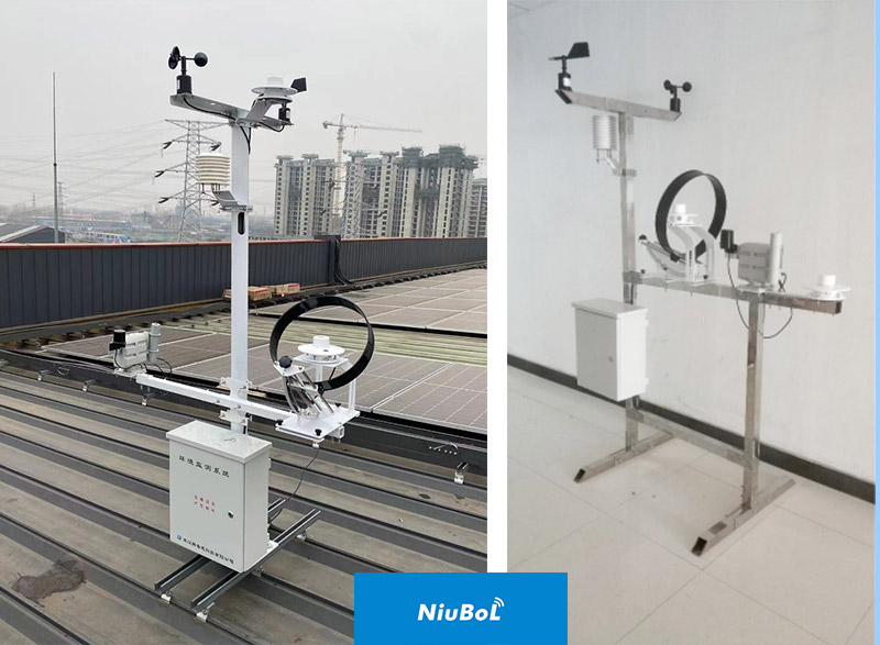
Useful PV weather station alarms tell the operator what was observed and what to check next. Separate irradiance, air and module temperature, wind validity and electrical equipment status. With correctly configured NiuBoL sensing channels and a tested notification path, the station supports investigation without claiming that every unusual reading identifies a plant fault.
 NBL-W-SRS-Solar-radiation-sensor-instruction-manual-V4.0.pdf
NBL-W-HPRS-Solar-Radiation-Sensor-Instruction-Manual-V3.0.pdf
Prev:PV Pyranometer Signal Chain: Raw Millivolts, Transmitters or RS485?
Next:PV Weather Station Offline Data: What Survives a Network Outage?
Related recommendations
Sensors & Weather Stations Catalog
Agriculture Sensors and Weather Stations Catalog-NiuBoL.pdf
Weather Stations Catalog-NiuBoL.pdf
Agriculture Sensors Catalog-NiuBoL.pdf
Water Quality Sensor Catalog-NiuBoL.pdf
Related products
 Combined air temperature and relative humidity sensor
 TDR Soil Moisture & Temperature Sensor for irrigation| RS485 |4-20mA| NBL-S-THR
 Soil pH sensor RS485 soil Testing instrument soil ph meter for agriculture |NBL-S-PH
 Wind Speed sensor Output Modbus/RS485/Analog/0-5V/4-20mA
 Tipping bucket rain gauge for weather monitoring auto rainfall sensor RS485/Outdoor/stainless steel
 Pyranometer Solar Radiation Sensor 4-20mA/RS485


Screenshot, WhatsApp to identify the QR code
WhatsApp number:+8615367865107
(Click on WhatsApp to copy and add friends)

