





— Blogs —
—Products—
 Consumer hotline +8618073152920
WhatsApp:+8615367865107
Address:Room 102, District D, Houhu Industrial Park, Yuelu District, Changsha City, Hunan Province, China
Product knowledge
Time:2025-03-28 16:20:23 Popularity:1220
PV weather station measurements describe environmental conditions; electrical test instruments measure electrical behavior. Irradiance in W/m² and module temperature help interpret a photovoltaic test, but they do not measure an I-V curve, insulation resistance or electrical output power. Scope both parts separately so a weather-station quotation is not mistaken for a complete PV electrical testing package.
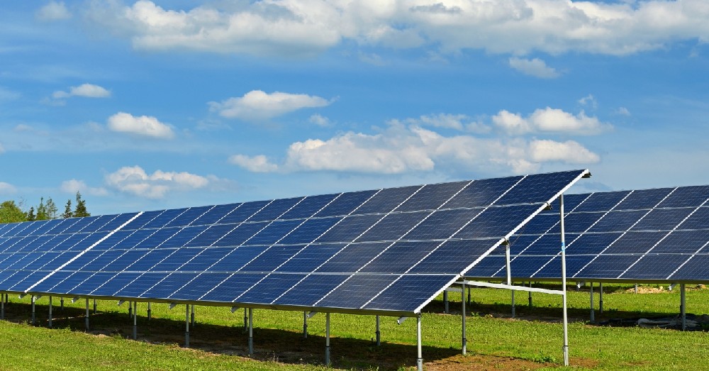
A contractor may receive a request for photovoltaic testing instruments when the actual requirement is a permanent weather station. Another project may need both electrical tests and environmental records. Clarify the deliverable before selecting hardware: a weather dataset, an electrical test result or an assessment combining the two.
PV module characterization includes current-versus-voltage measurement under defined conditions. The NLR module measurement service description distinguishes I-V measurements from the associated irradiance and temperature conditions. Environmental sensing supplies context; it is not a substitute for obtaining the electrical measurements.
| Question | Required observation | Boundary |
|---|---|---|
| What solar exposure reached the sensing plane? | Suitable irradiance measurement, W/m² | Not the module's electrical output |
| How warm was the represented module surface? | Contact temperature measurement, °C | Not a direct measurement of every cell temperature |
| What was the current-voltage behavior? | A suitable electrical I-V measurement | Not obtained from a weather sensor alone |
| What power or energy did the plant deliver? | Defined electrical meter or acquisition source, W/kW or Wh/kWh | Not the same quantity as irradiance or irradiation |
| Did the installation meet an electrical safety requirement? | The relevant electrical inspection and tests | Not established by a normal weather dashboard |
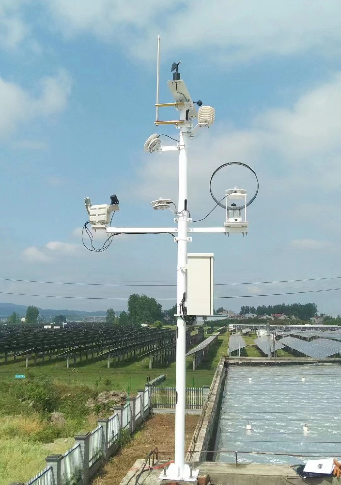
W/m² describes radiant power arriving per area at the sensor's plane. W describes electrical power at a defined electrical boundary. Multiplying irradiance by module area gives incident radiant power, not the measured electrical output. Conversion behavior, operating conditions and the electrical measurement remain relevant.
Likewise, integrating irradiance over time produces irradiation, commonly expressed in Wh/m² or kWh/m². It does not produce metered plant energy in kWh. Keep the quantities and their units in separate fields rather than relabelling a radiation total as generation.
As a dimensional illustration, a constant 800 W/m² for half an hour represents 400 Wh/m² of irradiation. This is not an achieved module output or a prediction of generation. An electrical-energy comparison still requires the appropriate plant record and a defined analysis method.
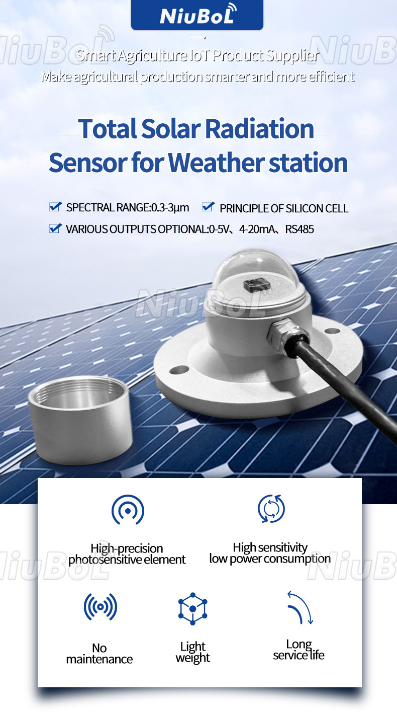
The NBL-W-SRS solar-radiation sensor provides a radiation observation when selected and installed appropriately. The sensor alone does not include a sun-tracking mechanism or provide separate direct-normal irradiance. Specify the intended plane, radiation component and any additional equipment needed for that measurement.
A horizontal measurement is not automatically the irradiance incident on a tilted module. If an electrical test concerns one array orientation, identify the environmental reference that represents it. With several orientations, review the coverage rather than assigning one weather channel to every test point without assessment.
| NiuBoL component | Relevant specification | Role and limitation |
|---|---|---|
| NBL-W-SRS | 0-1500 W/m²; stated spectral range 0.3-3 µm; response less than 5 seconds; selected analog or RS485 output | Solar-radiation observation; not an I-V tester |
| NBL-W-HPRS | 0-2000 W/m²; spectral range 0.3-3 µm; response ≤35 seconds to 99% | Thermopile irradiance measurement; confirm output version and suitability for the test method |
| NBL-W-PPT | -50°C to 100°C; stated accuracy ±0.5°C; selected RS485 or analog output | Module back-surface contact measurement at the installed point |
| NBL-W-LBTH | Air temperature -40°C to 80°C, ±0.5°C; humidity 0-100% RH, ±5% RH | Ambient context; not a replacement for the module contact probe |
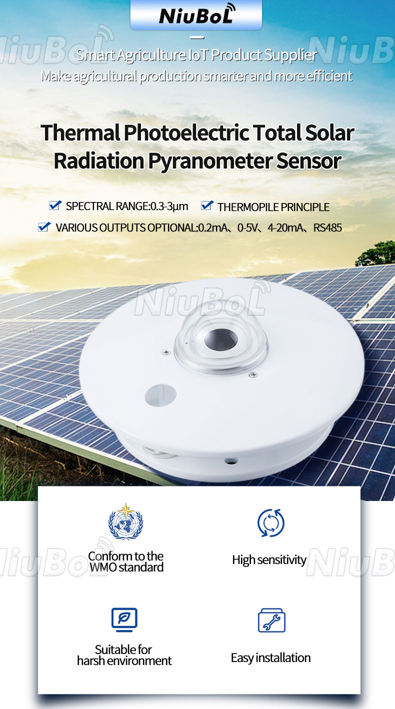
Separate sensor response, sampling interval and transmission interval. Polling a pyranometer every second does not turn its physical response into an instantaneous measurement. A rapidly changing irradiance condition can matter during an electrical test even when all records have correct timestamps.
For a short test, review the required environmental response and time alignment with the test provider. A long reporting average may hide variation during an I-V sweep. Retain observations appropriate to the test window; do not assume a five-minute dashboard value describes the conditions throughout a much shorter measurement.
Also verify what the temperature probe represents. Contact with the back surface, location and attachment affect interpretation. Do not call the air-temperature channel cell temperature or treat one surface probe as a thermal image of the entire module.
A compatible data logger can collect the environmental outputs and exchange data with another system. The TG462 / TG462S family offers RS485 and analog inputs plus network functions for configured acquisition. Interface availability does not establish that it can directly measure PV string voltage or current within the required electrical limits.
Keep PV conductors out of ordinary low-voltage sensor inputs unless a specifically rated and approved measurement arrangement provides the required isolation and conversion. Electrical testing and connection work must follow the project's qualified procedures. A shared RS485 network is a data path, not an electrical safety test.
Where a compatible meter or test instrument provides records, define their source, units, timestamps and identifiers alongside the weather channels. Confirm the actual protocol, map or file exchange. Do not attribute a customer's electrical test function to a gateway merely because it receives the result.
Before a test campaign, identify the represented module or array, the irradiance plane and the temperature probe location. Check the clocks and time zones of the acquisition systems. Record the start and end of the electrical test, not just the time an exported file was created. For repeated trials, define comparable outdoor PV test conditions before comparing results.
Run a supervised acquisition trial and verify the final records together. Confirm that changing the environmental channel labels or replacing a probe does not silently associate a different reference with the same test identifier. Identify missing or unsuitable periods rather than filling them with an unrelated station value.
A complete dataset can still be unsuitable for a claimed test method. Confirm the required instruments, calibration scope and procedure with the responsible test organization. A generic component accuracy statement is not evidence that the complete arrangement meets an unstated standard.
List the weather instruments, electrical instruments, mounting, acquisition and analysis as separate deliverables. State who provides the electrical measurements and who joins the records. This prevents a lower-priced weather-only offer from being compared with a package that includes electrical tests and reporting.
For a NiuBoL environmental-sensing enquiry, provide the intended electrical test or monitoring activity, required weather quantities, exposure, timing needs and receiving interfaces. Ask for the relevant output versions and calibration arrangements. Do not assume an environmental sensor price includes electrical test equipment, an accredited report or a guaranteed generation improvement.
The weather package should contain channel locations, mounting geometry, instrument identity, interval definitions and records that can be aligned with the test period. The electrical package should contain the test instrument, method, safety arrangements and the electrical results. If one contractor delivers both, the acceptance checklist should still keep the responsibilities separate. An irradiance value can support the interpretation of a performance test; it is not itself an I-V curve, insulation test or measured electrical output.
Before a short field test, ask how the two time bases are synchronized. A weather logger may report an interval mean while an electrical tester records a momentary sweep. The team should identify whether the irradiance sensor is on the relevant plane and whether the module temperature point represents the tested array. A well-installed station cannot rescue a comparison made against the wrong plane or time window.
The quotation should name who supplies any temporary sensors or reference instruments, who verifies their scaling and who retains the joint dataset. Without those details, buyers can compare two offers that appear to include 'PV testing' but have entirely different deliverables. This is a scope boundary, not a claim that the station has an electrical certification function.
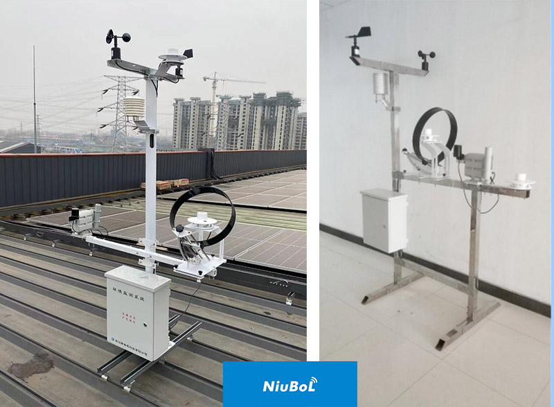
Not by itself. It supplies environmental measurements. The I-V result requires suitable electrical test equipment and a defined procedure; the weather record can then be associated with that result.
No. It represents incident radiant power for the defined exposure, not electrical power at the module or inverter. Obtain the electrical quantity from a suitable measured source.
No. The NBL-W-PPT provides a local contact surface measurement, while an atmospheric sensor measures air conditions. Keep their identities and installation positions distinct in the record.
No. Physical response, reporting averages and clock alignment still matter. Assess the selected sensor and retained records against the actual test duration and method.
No. RS485 concerns communication. Voltage ratings, isolation, protection and approved connection procedures are separate requirements. Do not connect PV string circuits directly to ordinary weather inputs.
They may, but their deliverables and responsibilities must remain explicit. Identify the environmental instruments, electrical test scope, acquisition, analysis and reporting so offers can be compared on the same basis.
Not unless the required testing and reporting service is explicitly included and supported. Define the method and responsible organization before treating an equipment purchase as a test-service contract.
Assign the weather-data owner and the electrical-test owner separately. Agree sensor location, timestamp alignment, applicable irradiance plane and data export before the test. The test team can then pair valid environmental observations with its electrical measurements without treating the station as the electrical instrument.
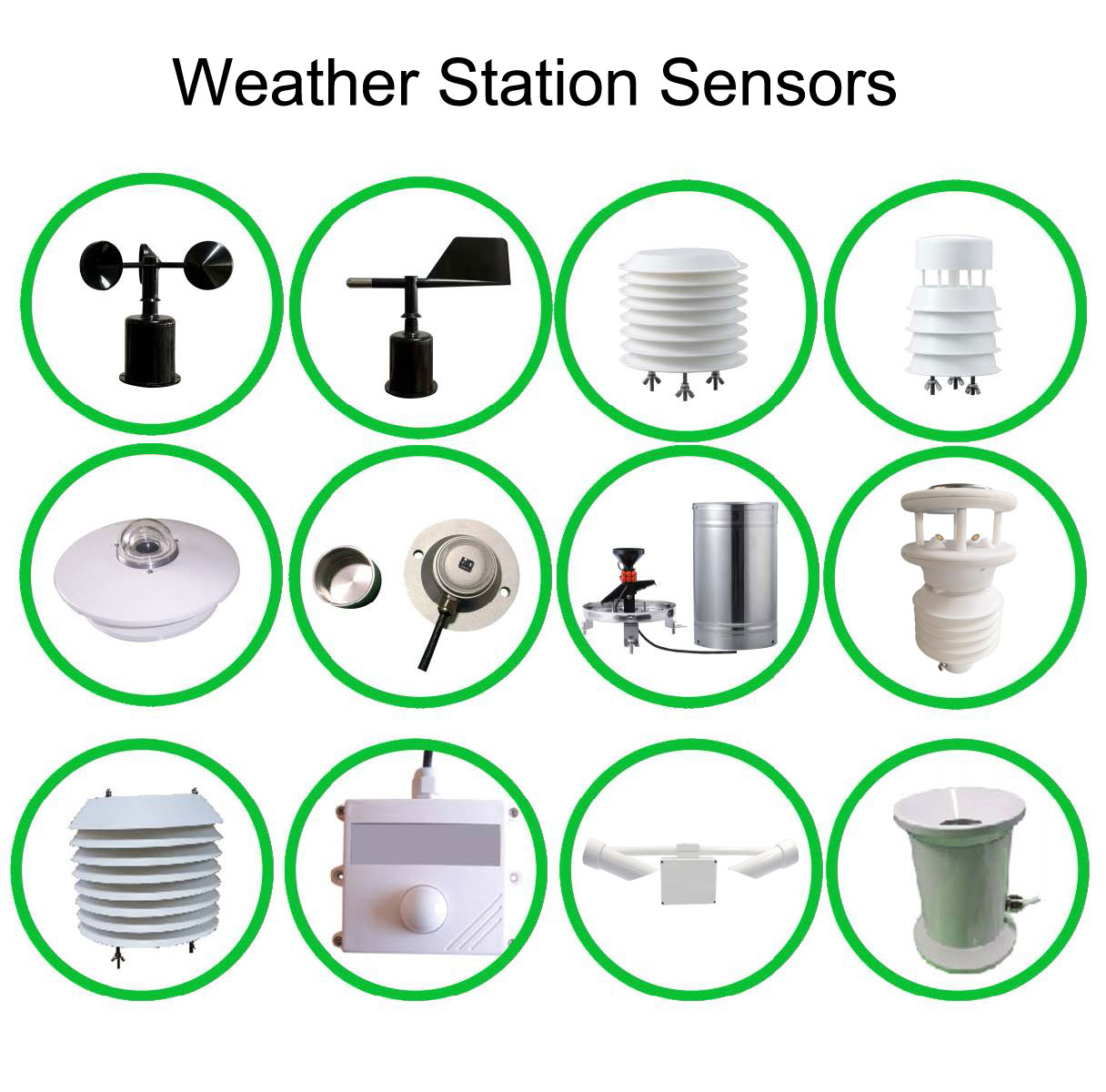
PV weather station measurements and electrical test results answer complementary questions. Select NiuBoL environmental sensors for the required exposure and timing, obtain the electrical measurements separately, and verify how the records relate. Clear measurement responsibility is more useful than a quotation that calls every device a photovoltaic tester.
 NBL-W-SRS-Solar-radiation-sensor-instruction-manual-V4.0.pdf
NBL-W-HPRS-Solar-Radiation-Sensor-Instruction-Manual-V3.0.pdf
Prev:Solar-Powered Weather Station vs PV Monitoring: Two Different Requirements
Next:Ultrasonic Weather Station Light Channels: Lux or Solar Irradiance?
Related recommendations
Sensors & Weather Stations Catalog
Agriculture Sensors and Weather Stations Catalog-NiuBoL.pdf
Weather Stations Catalog-NiuBoL.pdf
Agriculture Sensors Catalog-NiuBoL.pdf
Water Quality Sensor Catalog-NiuBoL.pdf
Related products
 Combined air temperature and relative humidity sensor
 TDR Soil Moisture & Temperature Sensor for irrigation| RS485 |4-20mA| NBL-S-THR
 Soil pH sensor RS485 soil Testing instrument soil ph meter for agriculture |NBL-S-PH
 Wind Speed sensor Output Modbus/RS485/Analog/0-5V/4-20mA
 Tipping bucket rain gauge for weather monitoring auto rainfall sensor RS485/Outdoor/stainless steel
 Pyranometer Solar Radiation Sensor 4-20mA/RS485


Screenshot, WhatsApp to identify the QR code
WhatsApp number:+8615367865107
(Click on WhatsApp to copy and add friends)

