





— Blogs —
—Products—
 Consumer hotline +8618073152920
WhatsApp:+8615367865107
Address:Room 102, District D, Houhu Industrial Park, Yuelu District, Changsha City, Hunan Province, China
Product knowledge
Time:2024-12-14 19:44:35 Popularity:2566
A remote rain gauge combines a rainfall sensor with acquisition, power and communications equipment so precipitation records can be viewed away from the site. The NiuBoL NBL-W-RS tipping-bucket sensor can form the measurement element of such a system. Its standard 0.2 mm resolution, liquid-rain operating limits and selected output version must be matched to the logger; remote transmission does not change the underlying gauge accuracy.

Rain entering a known collection area is guided into a tipping mechanism. Each completed tip corresponds to a defined rainfall increment. The acquisition system counts those increments or reads the rainfall value from the selected transmitter. It can then store observations and send records to a remote monitoring application.
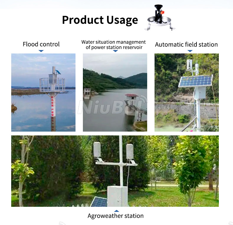
This makes a remote rain gauge useful for farm rainfall records, catchment observation and drainage monitoring. It does not directly measure river level, identify pollutants in rainwater or establish the severity of flooding. Those tasks need additional measurements and analysis. A rainfall station may provide an input to a warning system, but the gauge and modem alone are not the warning system.
The table below applies to the standard stainless-steel NBL-W-RS sensor. A solar supply, logger, cabinet, modem and mounting structure are separate system components. Their ratings and consumption must be specified for the offered assembly rather than inferred from the sensor.
| Parameter | Sensor specification | Practical meaning |
|---|---|---|
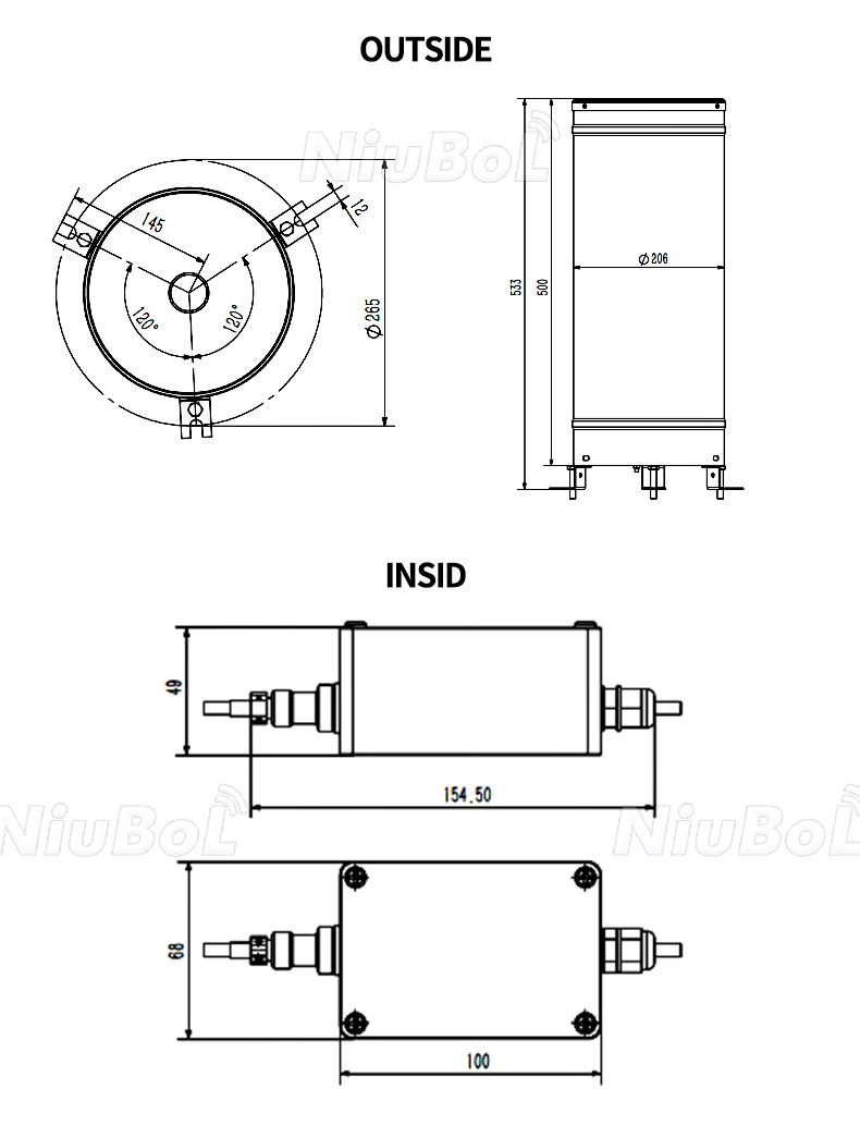
| Collection diameter | 200 +/-0.6 mm | Use this collection area when relating test water volume to rain depth. |
| Rainfall intensity range | 0-4 mm/min | Do not assume the accuracy statement covers higher intensities. |
| Resolution | 0.2 mm; approximately 6.28 mL per tip | A small rain depth is resolved in increments, not as a continuous analog depth. |
| Stated accuracy | +/-4%, indoor static test at 2 mm/min | Preserve the test condition when comparing performance. |
| Power options | DC 5 V or DC 12-24 V, according to version | Match the purchased version and wiring; do not apply either supply indiscriminately. |
| Output options | Reed-switch contact, 0-2.5 V, 0-5 V or RS485 | Select the logger input or digital interface accordingly. |
| Standard cable | 5 m | Check the actual route and cable specification before extending it. |
| Operating temperature | 0-50 C | This standard configuration is for liquid precipitation, not unattended freezing-weather operation. |
| Storage temperature | -40 to +80 C | A storage rating does not establish measurement capability in ice or snow. |
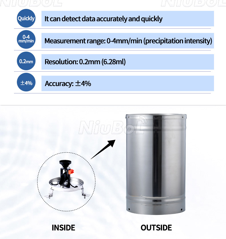
The NBL-W-RS product specifications distinguish resolution from accuracy. A 0.2 mm tip size does not mean +/-0.2 mm accuracy, and a different 0.1 mm gauge should not be represented as the same standard configuration. Likewise, no complete-station IP68 rating follows from using an outdoor rainfall sensor.
With a reed-switch version, connect the gauge to a compatible pulse-counting input. Establish the rainfall increment, contact handling and behavior after a logger restart. Count a known number of tips during commissioning and verify the resulting rain depth. For a 0.2 mm configuration, ten valid tips represent 2.0 mm; this checks channel scaling but is not a calibration of collection performance.
With the RS485 version, confirm Modbus RTU settings and the register map for the delivered transmitter. Check whether the value represents a cumulative total, an interval amount or another quantity, and determine its reset behavior. The NBL-W-RS protocol uses a scaled rainfall value; copying a register directly to the dashboard without its scale can create a tenfold error.
Do not sum repeated readings of a cumulative total as though they were interval rainfall. Calculate the change between valid readings, then handle any counter reset or rollover explicitly. When the sensor or logger is replaced, record the new baseline. Otherwise a maintenance event can appear as negative rainfall or an implausible storm.
For a sensor shared with other RS485 instruments, use a unique address and compatible serial settings. A gateway with general digital inputs is not automatically a validated rain counter. The data acquisition equipment should be configured and tested for the chosen rain-gauge signal, not selected only for cellular connectivity.
Choose a location that avoids roof runoff, overhead foliage, irrigation spray and nearby surfaces that splash water into the collector. Consider wind exposure and surrounding obstructions when judging how representative the measurement will be. A convenient roof location can be unsuitable if the project needs rainfall representative of an open field.
Fix the base firmly, center the leveling bubble using the adjustment screws and recheck it after tightening. Remove the transport restraint before testing the mechanism. Route the cable so it cannot pull on the assembly or collect water at an unprotected entry. Do not change the calibrated adjustment to compensate for an unexplained dashboard discrepancy.
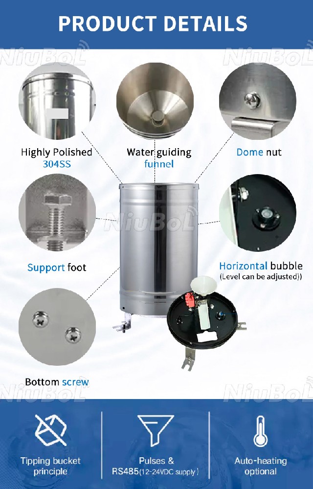
First observe free movement of the mechanism and receipt of the associated input at the logger. Then use a controlled water test. Slowly introduce a measured volume at a known rate and compare the collected rainfall increment with the expected depth. Fast pouring tests a different condition and may exceed the stated intensity range, so it cannot establish the published accuracy.
For a 200 mm diameter collector, the nominal area is approximately 31,416 mm2. A 314 mL test volume corresponds to about 10 mm of water depth, calculated as volume divided by collection area. This is an illustrative setup check; final calibration should use the specified procedure, suitable volume measurement and controlled delivery rate.
In an irrigation project, define whether rainfall should inhibit watering immediately, modify the next irrigation schedule or simply support later review. A rain gauge at one location may not represent rainfall across separated fields. Soil-moisture readings can help assess the crop root zone, but rainfall depth and soil water content remain separate measurements.
In a catchment or reservoir project, station position and reporting delay affect usefulness. Rainfall can provide context for water-level changes, but converting it into inflow or a flood threshold needs catchment information and an appropriate method. Pair rainfall with water-level observations where that is the actual management question.
For urban drainage, retain interval definitions and observation times so short bursts are not hidden inside daily totals. Tipping-bucket intensity is quantized: one 0.2 mm tip within a one-minute bin corresponds to a 12 mm/h bin rate, but that calculation does not prove rainfall was constant at that intensity. Short-interval records require careful interpretation, particularly in light rain.
A remote monitoring application should show both rainfall and record age. No new transmission does not mean no rain. Store observation timestamps at acquisition, distinguish them from server receipt times and define what happens when the network returns. Duplicate uploads must not add the same rainfall twice.
A cumulative value read after reconnection may recover the total amount without recovering the timing of individual tips. If storm timing matters, specify the required local event or interval records and test their recovery. A solar supply must cover the gauge interface, logger and modem; panel size cannot be inferred from the rain sensor's small signal alone.
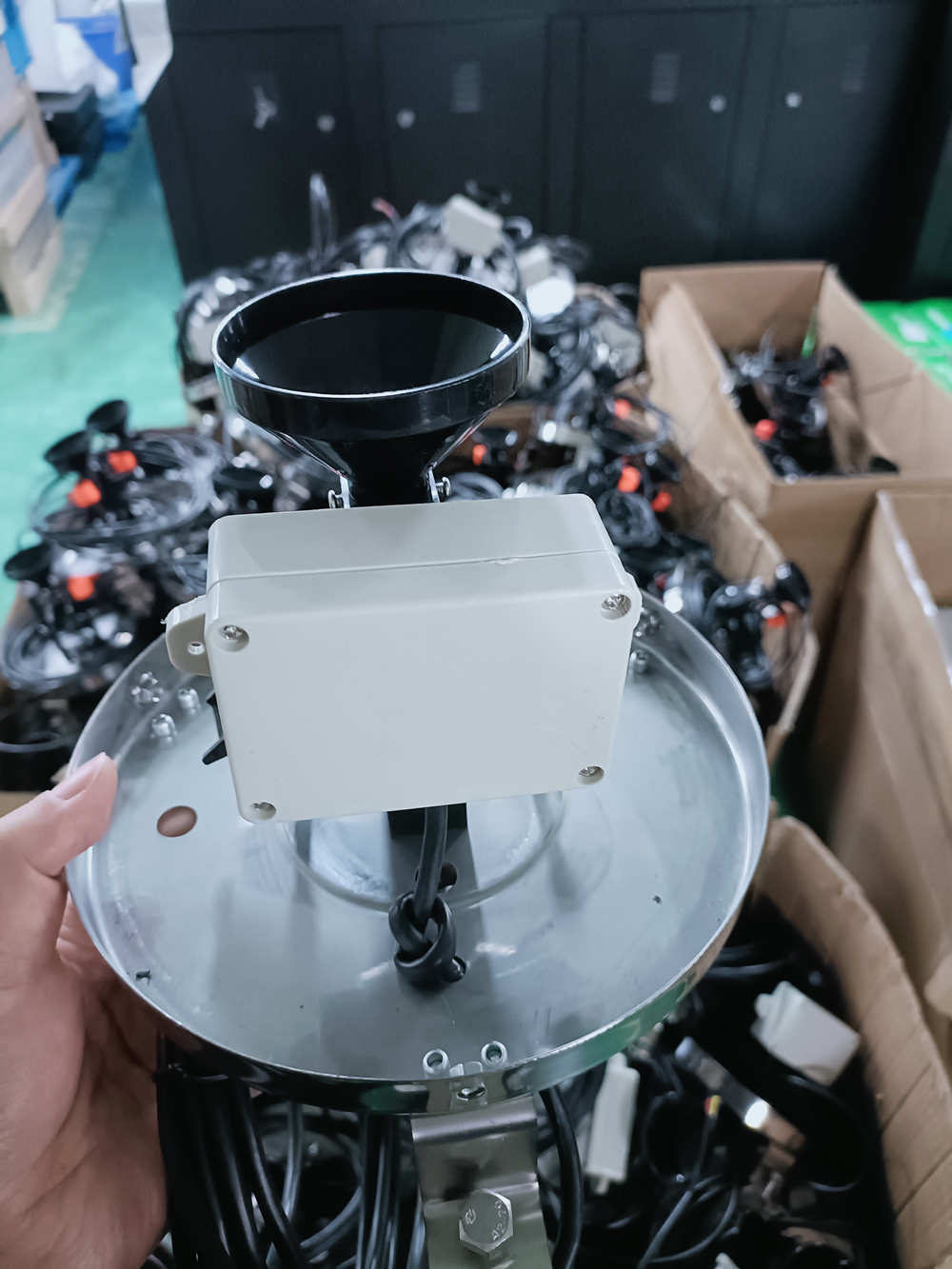
When expected rainfall remains zero, inspect the funnel, filter and transport restraint first, then check the mechanism, contact or RS485 response and logger channel. Compare the local channel with the remote record. If the local value advances but the server does not, the fault is in mapping or transmission rather than collection.
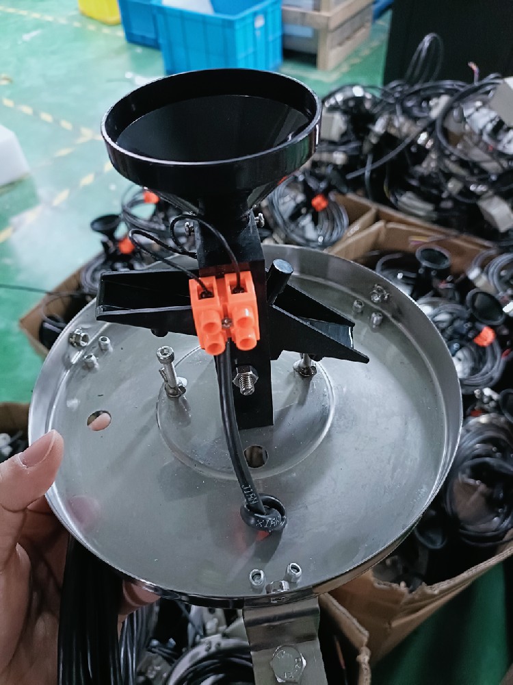
For excessive increments, inspect vibration, contact bounce, accidental water entry and incorrect scale settings. Compare counted tips with reported depth. Clean leaves, sediment and insects from the water path, and inspect the leveling bubble after service. The ABS gauge pictured below is an alternative construction; select it from its own specifications rather than transferring the stainless-steel model's ratings to it.
The standard NBL-W-RS operating range starts at 0 C, and its maintenance instructions require stopping operation during freezing conditions. If snow, icing or heated precipitation measurement is required, request an appropriate alternative and include heater consumption in the power design. A low storage-temperature rating does not resolve this limitation.
It needs a compatible acquisition function, which may be a dedicated logger or a suitable existing station controller. Match contact, analog or RS485 output to that equipment, then provide the required recording and remote communication functions.
No. It is the standard rainfall resolution. The stated accuracy is +/-4% under an indoor static test at 2 mm/min. Neither figure should be substituted for the other when writing a purchase specification.
Not as a standard liquid-rain installation operating below its 0-50 C range. Freezing conditions require a different agreed measurement arrangement. Request suitable precipitation equipment instead of assuming a solar-powered rain station includes heating.
Yes, with a compatible selected output and configured acquisition path. For Modbus RTU, obtain the delivered register map, units, scale and cumulative-value behavior. For a private platform, also agree the outgoing format and timestamp handling.
Provide the installation climate and country, rainfall reporting interval, preferred output, available network and power, mounting arrangement and intended receiving system. State whether storm timing, outage recovery and freezing-weather measurement are required. These requirements determine more than the gauge alone.
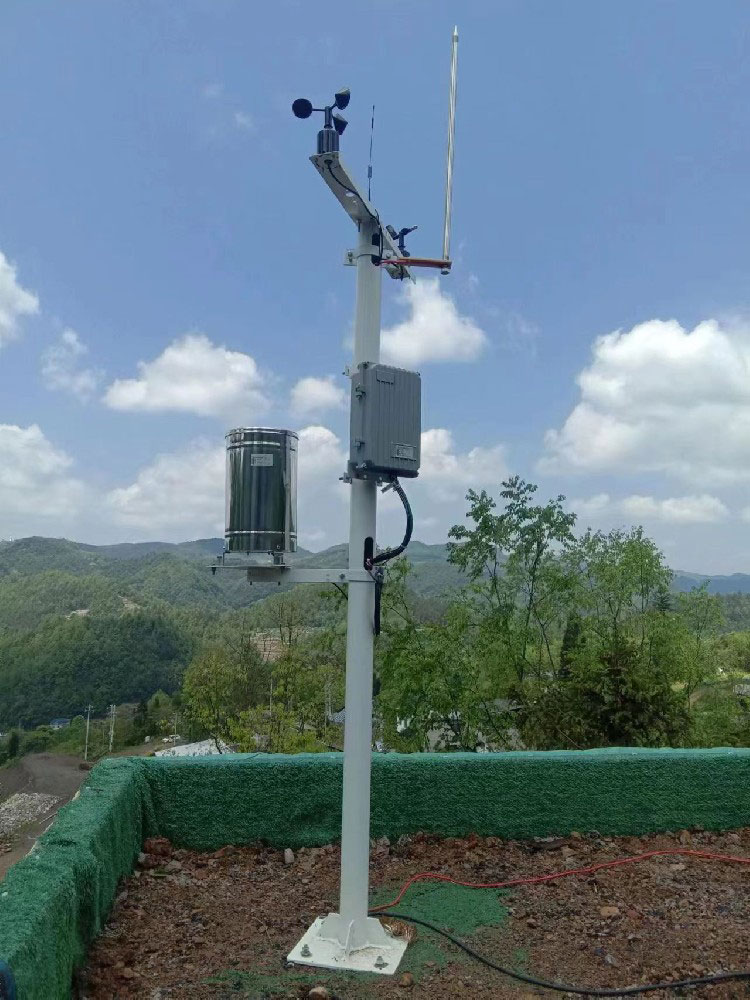
A useful remote rain gauge preserves the relationship between collected water, measured increments and correctly timed remote records. Select the sensor output, acquisition method and operating environment together. NiuBoL can review the rainfall measurement requirement and propose the gauge, logger, communications and power components without treating optional equipment as part of every configuration.
NBL-W-RS rain sensor instruction manual V4.0.

Prev:Commercial Weather Station: Building a Comparable Site Record
Next:Weather Station Purchase Specification: Build an Itemized Equipment Order
Related recommendations
Sensors & Weather Stations Catalog
 Agriculture Sensors and Weather Stations Catalog-NiuBoL.pdf
Weather Stations Catalog-NiuBoL.pdf
Agriculture Sensors Catalog-NiuBoL.pdf
Water Quality Sensor Catalog-NiuBoL.pdf
Related products
 Combined air temperature and relative humidity sensor
 TDR Soil Moisture & Temperature Sensor for irrigation| RS485 |4-20mA| NBL-S-THR
 Soil pH sensor RS485 soil Testing instrument soil ph meter for agriculture |NBL-S-PH
 Wind Speed sensor Output Modbus/RS485/Analog/0-5V/4-20mA
 Tipping bucket rain gauge for weather monitoring auto rainfall sensor RS485/Outdoor/stainless steel
 Pyranometer Solar Radiation Sensor 4-20mA/RS485


Screenshot, WhatsApp to identify the QR code
WhatsApp number:+8615367865107
(Click on WhatsApp to copy and add friends)

