





— Blogs —
—Products—
 Consumer hotline +8618073152920
WhatsApp:+8615367865107
Address:Room 102, District D, Houhu Industrial Park, Yuelu District, Changsha City, Hunan Province, China
Product knowledge
Time:2024-10-19 21:14:44 Popularity:2034
Small weather station installation requires a model-specific direction check: the NiuBoL NBL-W-DS wind vane uses a white south reference mark, while the NBL-W-51MUWS ultrasonic head uses a north reference. Align the specified mark with the corresponding geographic direction, secure the bracket, then verify the direction at the logger. A fixed angular error will remain in every reading even when communication is working correctly.
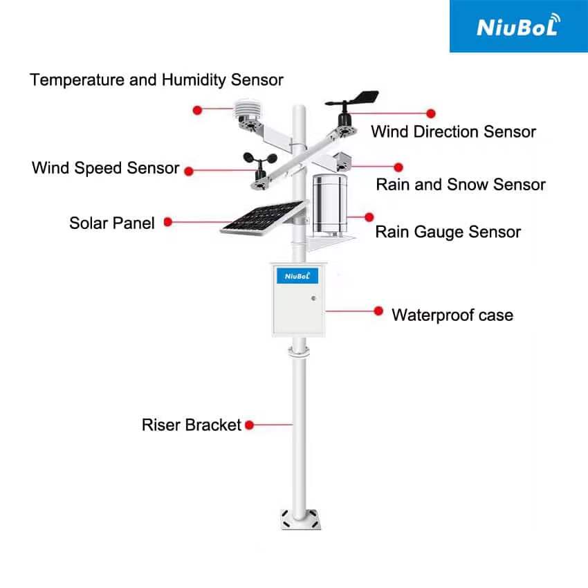
The wind vane, its housing and the mounting arm do not necessarily share the same reference. The moving vane follows the wind; the stationary reference identifies how the instrument must be mounted. Pointing the vane by hand without orienting the sensor body does not establish a correct installation.
For the NBL-W-DS wind direction sensor, align the white south mark with geographic south. For the NBL-W-51MUWS ultrasonic weather sensor, align the north reference with geographic north. Do not transfer one model's instruction to another simply because both report direction in degrees.
| Instrument or observation | Installation check | What a successful check establishes |
|---|---|---|
| NBL-W-DS mechanical wind vane | White south reference faces geographic south; bracket is level and vane moves freely. | The housing reference is aligned. Free movement alone does not verify the reported angle. |
| NBL-W-51MUWS integrated ultrasonic head | North reference faces geographic north; head is level and the acoustic paths are unobstructed. | The head has the intended directional reference and mounting attitude. |
| Logger wind direction channel | Check units, scaling and any configured direction offset. | The receiving system interprets the sensor output without adding an unintended correction. |
| Direction convention | Use the direction from which the wind comes, not the direction toward which it travels. | Displayed compass labels and exported degrees describe the same observation. |
A magnetic compass indicates magnetic north, not automatically geographic north. Account for the local magnetic declination or use an established surveyed reference. Keep the compass away from steel mast sections, electrical cabinets and other sources of local magnetic disturbance. Record the reference method so a replacement technician can reproduce the alignment.
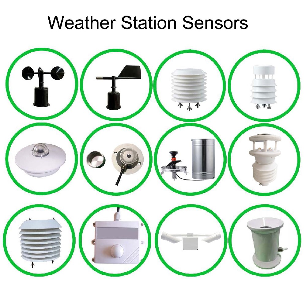
Small weather station installation can appear complete because the display shows a plausible direction. A number that changes is evidence of a signal, not evidence that its reference is correct. Finish the mechanical alignment first, then examine the measurement and the receiving channel separately.
Keep offsets in one documented location. Correcting the same mounting error in both the sensor and the logger can create a second error when either device is replaced. Where adjustment is required, identify which device owns the correction and repeat the check after saving its configuration.
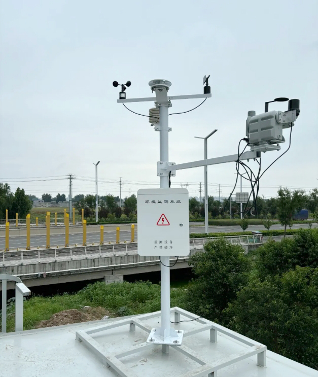
A direction error that remains similar across several known vane positions suggests an orientation or offset problem. An error that appears mainly when wind comes past a building may instead reflect disturbed airflow. Moving a software offset until one observation agrees will not repair turbulence around an unsuitable site.
Choose an open observation location, but do not treat a universal 10 m clearance or a 25 m square plot as sufficient for every station. The height and geometry of nearby structures, measurement height and purpose of the record matter. A rooftop airflow study and an open-field weather record do not describe the same exposure.
Check adjacent measurements independently. Keep a rain-gauge opening clear of overhanging equipment and runoff from the mast or solar panel. Keep an air-temperature radiation shield ventilated and away from exhausts or heated walls. Placing the whole station in shade to improve temperature readings can obstruct wind and rainfall or compromise solar charging.
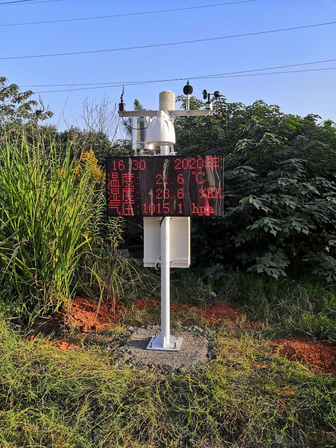
Not every weather sensor produces pulses. Rain-gauge contacts, analog transmitters and RS485 devices require different inputs. Match the actual ordered output to the logger channel before connecting cables; a mechanically correct installation cannot compensate for a wrong electrical interface.
For an RS485 Modbus RTU version, check supply voltage at the connected instrument, polarity, address, serial settings and the direction register's units and scale. RS485 identifies the electrical interface; it does not make every connected device use the same protocol or register layout. Keep cable joints protected and route measurement wiring away from high-current switching circuits using the project's cable and grounding design.
If a sensor communicates on a short service lead but fails through the installed cable, inspect the cable route, joins, power drop and bus configuration before rotating the head or changing its direction offset. If raw values are stable but compass labels disagree, inspect the display mapping instead.

Use a foundation, anchors and mast arrangement designed for the site loads and ground conditions. Expansion anchors are not a universal solution for every concrete base or soil. After tightening, recheck mast attitude, head level and the directional reference; a small movement at the clamp can alter the reading without leaving an obvious electrical fault.
Provide strain relief so cable weight or wind movement cannot rotate a sensor housing or pull a connector. Check clearance around the vane and wind cups through their full movement. Nearby visibility instruments, panels and support arms must not block the wind sensor or rain opening.
Lightning protection requires a coordinated design for the mast, bonding, earth system and power and signal entry protection. Adding a rod beside a station does not by itself establish protection. Have the responsible electrical designer review the arrangement, and do not climb or service a mast during a thunderstorm.
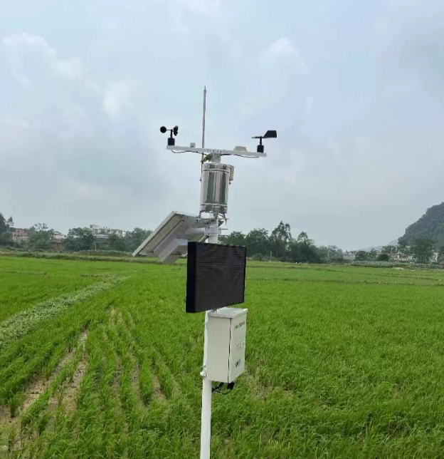
During routine maintenance, inspect sensor cleanliness, connections, logger records, batteries, solar-panel shading and fixings. Repeat the orientation check after a wind sensor is removed, a clamp is loosened, a mast is lowered or storm damage is repaired. Marking the original clamp position helps, but does not replace verifying the reference again.
Back up records and configuration before a logger update. Check the installed version's release information and repeat affected channel checks afterward instead of updating automatically during an observation campaign. Record maintenance times and flag values generated while instruments were handled.
A nearby weather service can help identify an unusual trend, but its readings do not calibrate a station with a different location, height or averaging period. Investigate persistent differences using an appropriate reference and comparable exposure. Do not adjust a local sensor just to make two dissimilar sites agree.
No. Follow the reference on the actual model. The NBL-W-DS white south mark faces geographic south; the NBL-W-51MUWS north reference faces geographic north. Orient the stationary body as specified, rather than copying another station's bracket position.
Check body alignment and direction offsets first, then compare raw sensor output with the receiving display. A fixed angular difference can come from installation or configuration. It is not sufficient evidence that the sensing element needs replacement.
It can correct a documented reference offset, but not airflow deflection that varies with wind direction and speed. Evaluate the observation location before applying a software correction to readings affected by an obstruction.
No. NBL-W-SS and NBL-W-DS are IP65-rated, but that rating does not establish freedom from icing, blocked movement, loose brackets or damaged connectors. Include these conditions in the maintenance inspection.
Send the exact model and output version, a photograph of its reference mark and bracket, the geographic alignment method, raw readings and displayed readings from the same time, and any configured offsets. These details distinguish a mounting problem from a receiving-channel problem.
For small weather station installation, establish the correct geographic reference before judging wind-direction accuracy. Recheck the alignment after tightening and maintenance, distinguish exposure errors from fixed offsets, and verify the receiving channel separately. NiuBoL can review the model-specific mounting and interface details when the installation photographs and configuration are available.
Prev:Industrial Weather Station: Weather Monitoring vs Hazard Detection
Next:Simple Weather Station: Define the Minimum Useful Configuration
Related recommendations
Sensors & Weather Stations Catalog
 Agriculture Sensors and Weather Stations Catalog-NiuBoL.pdf
Weather Stations Catalog-NiuBoL.pdf
Agriculture Sensors Catalog-NiuBoL.pdf
Water Quality Sensor Catalog-NiuBoL.pdf
Related products
 Combined air temperature and relative humidity sensor
 TDR Soil Moisture & Temperature Sensor for irrigation| RS485 |4-20mA| NBL-S-THR
 Soil pH sensor RS485 soil Testing instrument soil ph meter for agriculture |NBL-S-PH
 Wind Speed sensor Output Modbus/RS485/Analog/0-5V/4-20mA
 Tipping bucket rain gauge for weather monitoring auto rainfall sensor RS485/Outdoor/stainless steel
 Pyranometer Solar Radiation Sensor 4-20mA/RS485


Screenshot, WhatsApp to identify the QR code
WhatsApp number:+8615367865107
(Click on WhatsApp to copy and add friends)

