





— Blogs —
—Products—
 Consumer hotline +8618073152920
WhatsApp:+8615367865107
Address:Room 102, District D, Houhu Industrial Park, Yuelu District, Changsha City, Hunan Province, China
Product knowledge
Time:2026-02-09 15:09:45 Popularity:601
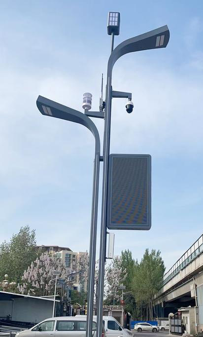
Smart pole weather instrument integration starts with two checks: whether the pole can power the instruments throughout the required observation period, and whether its controller can interpret their actual outputs. A mounting position and an available communications port are not enough. NiuBoL weather sensors can form part of a pole-mounted monitoring system, but the sensor, power converter, data logger and remote connection each have a separate job. Define those interfaces before selecting a combined head or several individual instruments.

A street light may have power only after dusk. Its weather instruments may be expected to observe daytime heat, rain and wind as well. Ask the lighting operator for the circuit schedule, cabinet drawing and available continuous auxiliary supply. Verify conditions at the intended connection point rather than assuming that a lit street at night has a continuously energized daytime cabinet.
Where an auxiliary battery is necessary, calculate the complete load. For illustration, a continuous 2 W sensor-and-controller load uses 48 Wh per day. At an assumed 80% conversion efficiency, supplying that load requires 60 Wh before battery reserve, temperature effects and battery aging are considered. These are example design inputs, not a NiuBoL station rating. Add the actual modem duty cycle and any heater separately; the lamp's rated power says nothing about the capacity available to the monitoring branch.
A separate cup anemometer is useful where wind speed needs its own mounting position or replacement path. Select its ordered output first: pulse, analog and digital variants require different controller inputs. A pole controller with an RS485 socket cannot count a pulse output through that socket. Keep the output type, scale and supply option together in the channel schedule.
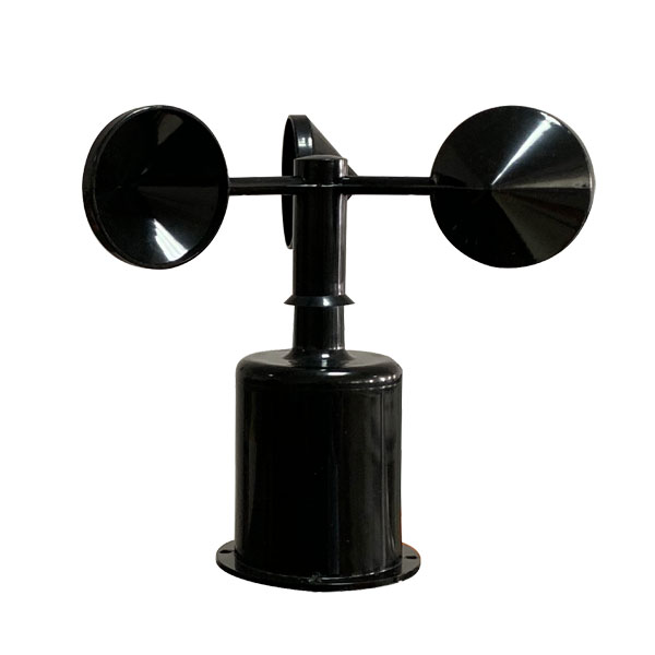
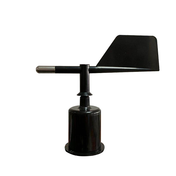
A wind vane adds a direction channel, not another speed value. Its north reference and output interpretation must remain consistent after maintenance. With digital direction, check units and invalid values; with analog direction, check the transfer function and endpoint behavior. NBL-W-SS wind speed and NBL-W-DS wind direction sensors have IP65 protection. That rating does not remove the need for suitable glands, connectors and strain relief in the pole assembly.
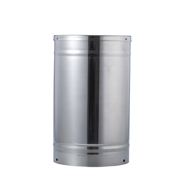
A tipping bucket rain gauge introduces a different electrical question. A contact-output configuration needs an appropriate counting input and contact handling, while a digital configuration needs its own interface definition. Confirm where accumulation is calculated and whether it survives a controller restart. If the counter resets at midnight, power restoration or maintenance, the receiving application needs that event to avoid reporting a negative rainfall increment.
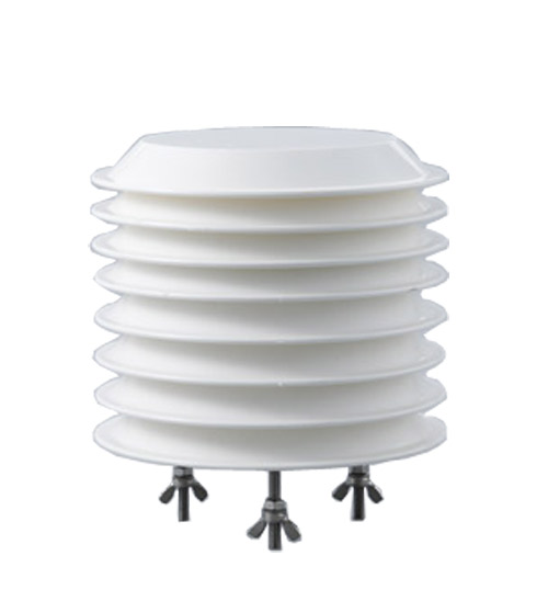
A shielded air temperature, humidity and pressure instrument can provide atmospheric channels without using the lighting cabinet as the measurement enclosure. Put the sensing head in representative outdoor air, away from converter exhaust and luminaire heat. Keep its service cable identifiable through the cabinet so a lighting repair does not accidentally disconnect an environmental channel or change its supply polarity.
A configurable ultrasonic weather sensor combines core weather channels through RS485 Modbus RTU. This can reduce separate field connections, but it also gives those channels a shared location. Confirm the selected parameter list and supply variant. A missing optional parameter is not a zero measurement, and an integrated head does not automatically include cellular transmission, a platform account or the pole controller driver.
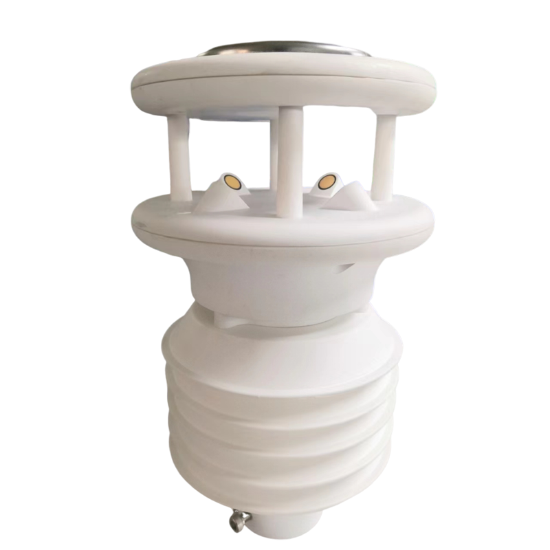
Solar irradiance needs an appropriate sensor orientation and an unobstructed view, as well as a compatible input. A thermopile millivolt output cannot be wired to an RS485 port without a suitable measurement interface; select the actual ordered output rather than assuming all sensors share the compact head's protocol. Define whether the required observation is horizontal irradiance or another plane before positioning the bracket.
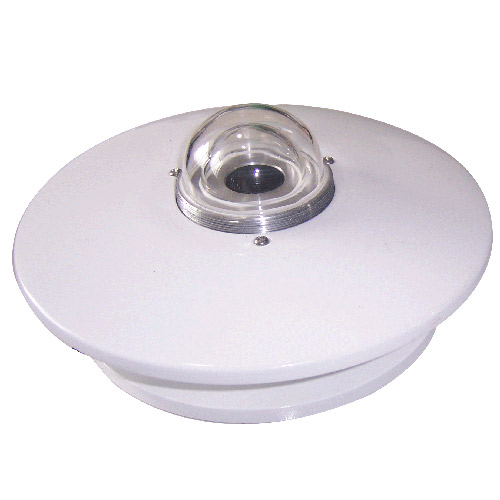
Ultraviolet radiation is a separate measurement from broadband solar irradiance and visible illuminance. Specify the UV quantity and units required by the application, together with output scaling. Do not name a generic radiation tag "UV index" unless the selected instrument and calculation provide that quantity. This distinction prevents a platform label from implying a measurement that the installed hardware cannot supply.
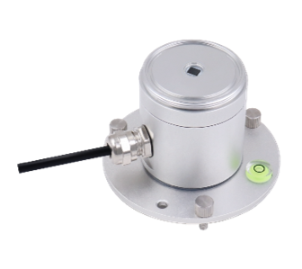
A particulate sensing inlet must remain exposed to the intended air, not sealed inside an IP-rated electrical box. For a roadside point, identify whether vehicle exhaust, resuspended road dust or wider neighborhood conditions are the monitoring target. The optical mass estimate, its calibration conditions and its maintenance needs belong in the instrument selection; a weather controller does not make it equivalent to a regulatory reference analyzer.
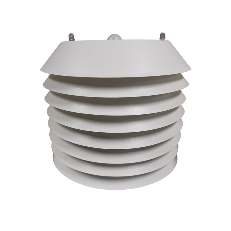
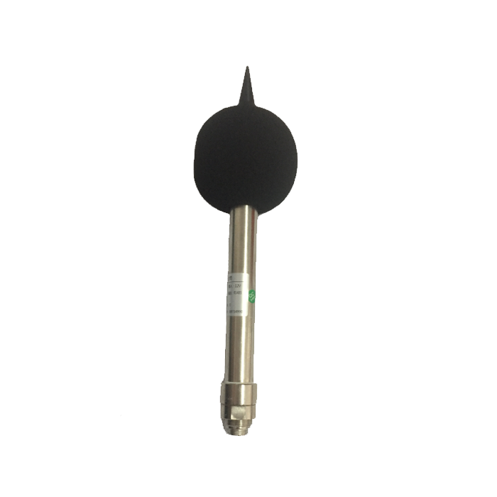
A noise sensor needs a mounting position that does not simply capture cabinet fans, vibrating brackets or the pole's own loudspeaker. Check the required acoustic quantity before creating an alarm. A sound-level value is not automatically LAeq for a specified interval. Frequency weighting, time weighting, averaging and field calibration must match the selected acoustic instrument and the project's reporting method.
A combined gas and particulate housing can serve a broader environmental package, but each gas channel still needs its own range, units and performance conditions. Ambient concentration monitoring is not a substitute for a certified personnel protection or emergency shutdown system. Request the exact installed channel list and calibration arrangements, rather than inferring all gas types from an enclosure photograph.
| Boundary | Integration check |
|---|---|
| Supply to instrument | Measure voltage at the head during controller start and modem transmission; check the selected instrument's limits. |
| Instrument to controller | Match physical interface, protocol, address, units and scale to the ordered variant. |
| Controller to server | Agree transport, authentication, payload fields, timestamps and missing-data handling. |
| Server to operator display | Show observation time and validity separately from message receipt time. |
| Lighting maintenance to monitoring | Confirm isolation points and what happens when the lighting branch is switched or serviced. |
For the configurable compact head, 9600 bps is the published serial setting, and the receiving system must use the selected version's register map. Do not apply that setting to every separate instrument. Start with one head and one controller, then check signed values, scales and unsupported channels before adding other addresses. Record a known sensor reading and compare it with the displayed engineering value.
Next, interrupt the upstream network while keeping the sensor bus connected. The platform should distinguish a communications interruption from a valid unchanged observation. Reconnect and verify whether buffered records, if that function is ordered, retain their observation timestamps. Repeat with a disconnected sensor. An old value held on screen without an age indicator is a different fault from a sensor legitimately measuring constant weather.
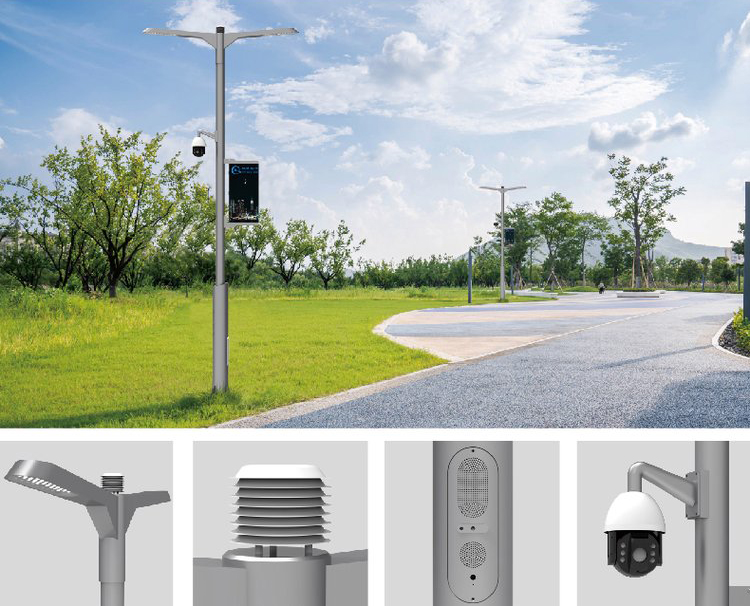
Have the pole owner assess the added mass, projected area, mounting method and cable route. Existing cameras, signs and antennas may already occupy the useful mounting space. Do not drill or clamp a structural pole based only on a sensor's dimensions. Maintain access to the luminaire and service door, and check that equipment can be removed safely without disturbing unrelated installations.
Outdoor wiring needs a coordinated earthing and surge-protection design appropriate to the whole installation. IP65 is an ingress classification, not lightning immunity. Route signal and power cables with the pole's electrical design, protect them at sharp edges and leave service loops where components must be lowered or replaced. Mains work and protection selection belong with appropriately qualified project personnel.
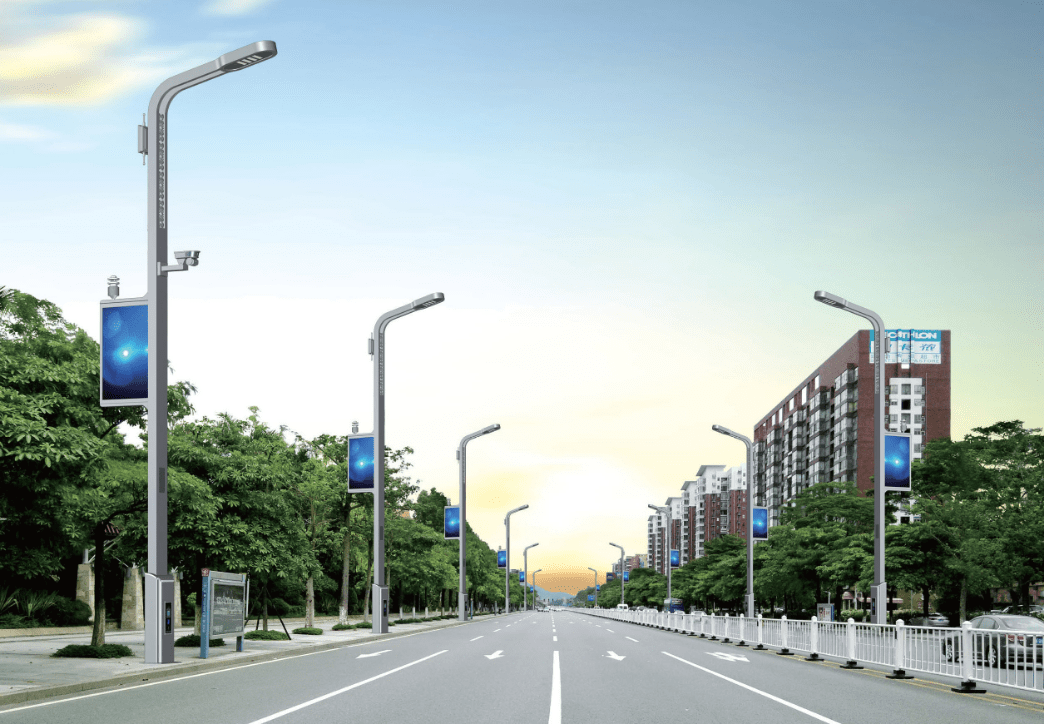
Before ordering a whole street, agree which measurements, input cards, converters, brackets and data services are included. Witness one complete installation through a daytime supply period and a lighting switching event. Check live readings, restart recovery, channel identity and server timestamps. Expand only after the actual controller configuration works; a list of supported protocol names is not a completed interoperability test.
For a NiuBoL application review, send the pole drawing, auxiliary power schedule, controller input list, required measurements and reporting format. Identify whether the enquiry concerns sensors only or the acquisition package as well. These details make a quotation comparable without inventing a universal per-pole price or promising that one wiring arrangement suits every city.
Only during energized periods unless a suitable independent supply or energy-storage arrangement is provided. Continuous observation requires a verified continuous energy path, sized for the complete installed load.
No. RS485 defines the electrical interface. The controller must also implement the instrument's protocol, register interpretation, timing and fault handling. Prove those functions with the ordered sensor version.
Not in the compact head described here. Its local output is RS485 Modbus RTU. Remote reporting requires the selected logger or gateway and an agreed server-side interface.
No. Build the load schedule from each selected device, including startup, transmission and heating states where applicable. Converter losses and power availability during lighting shutdowns also affect the design.
It should demonstrate continuous power for the required period, correct engineering values at the server, identifiable invalid and stale data, restart recovery and maintainable mounting. Agree pass conditions for that project before the test.
Smart pole weather instrument integration is successful when the installed measurements reach the operator with the correct units, time and validity through every lighting and network state. NiuBoL sensors provide the measurement inputs; the complete pole design must supply continuous power, compatible acquisition and a tested reporting path.
Prev:Solar Radiation Component Closure: Check GHI, DNI and DHI
Next:Street Lamp Weather Station Siting for Urban Microclimate Networks
Related recommendations
Sensors & Weather Stations Catalog
 Agriculture Sensors and Weather Stations Catalog-NiuBoL.pdf
Weather Stations Catalog-NiuBoL.pdf
Agriculture Sensors Catalog-NiuBoL.pdf
Water Quality Sensor Catalog-NiuBoL.pdf
Related products
 Combined air temperature and relative humidity sensor
 TDR Soil Moisture & Temperature Sensor for irrigation| RS485 |4-20mA| NBL-S-THR
 Soil pH sensor RS485 soil Testing instrument soil ph meter for agriculture |NBL-S-PH
 Wind Speed sensor Output Modbus/RS485/Analog/0-5V/4-20mA
 Tipping bucket rain gauge for weather monitoring auto rainfall sensor RS485/Outdoor/stainless steel
 Pyranometer Solar Radiation Sensor 4-20mA/RS485


Screenshot, WhatsApp to identify the QR code
WhatsApp number:+8615367865107
(Click on WhatsApp to copy and add friends)

