

— Blogs —
—Products—
 Consumer hotline +8618073152920
 WhatsApp:+8615367865107
Address:Room 102, District D, Houhu Industrial Park, Yuelu District, Changsha City, Hunan Province, China
Product knowledge
Time:2026-02-05 11:52:45 Popularity:506
In the context of accelerated construction of new power systems, the coupling between photovoltaic arrays and transmission lines continues to deepen. Micro-meteorological environmental parameters have evolved from simple "environmental reference data" to core decision variables for intelligent power station operations and maintenance. For system integrators and EPC contractors, the value of transmission line micro-meteorological monitoring systems lies not only in the accuracy of single-point data but also in their capability as edge perception nodes for deep integration with upper-level SCADA, EMS, and intelligent O&M platforms.
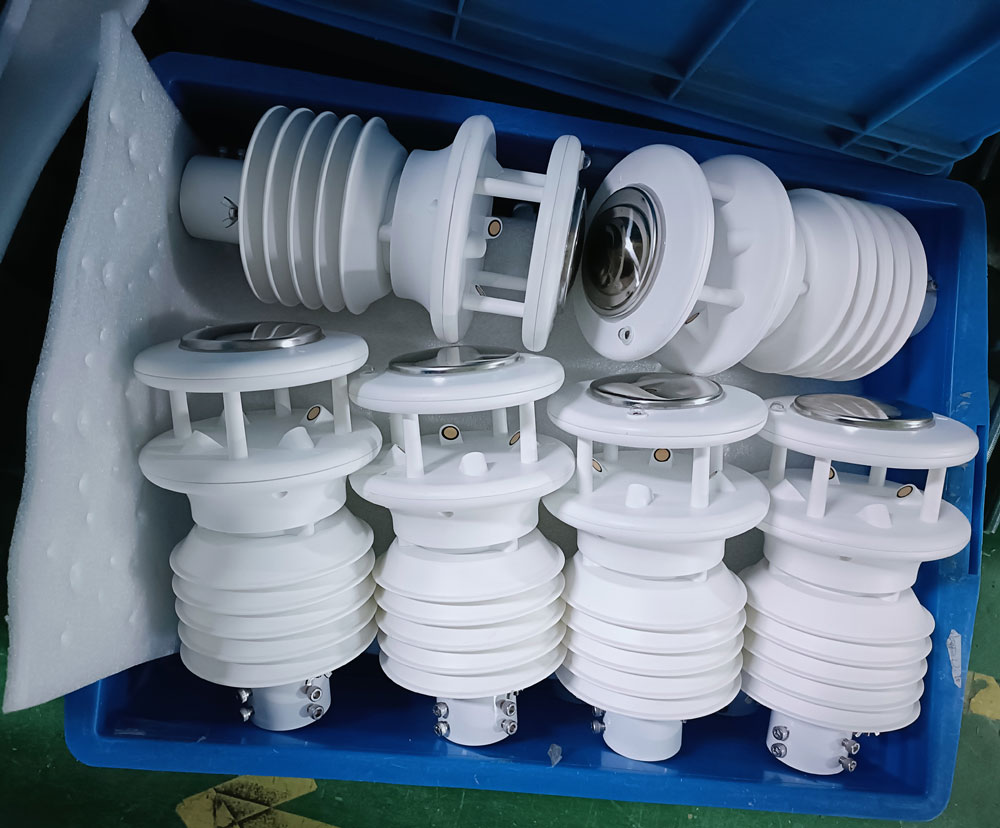
Based on more than ten years of project accumulation in industrial environmental monitoring, NiuBoL has developed a full-stack micro-meteorological monitoring solution covering sensor layer, communication layer, and platform layer for typical scenarios such as ground-mounted photovoltaic stations, mountainous distributed projects, and high-voltage transmission corridors. This article systematically explains the engineering selection logic, communication architecture design essentials, and typical project integration practices from the technical perspective of system integrators.

Wind-induced failure of photovoltaic support systems is a high-frequency risk in power station O&M. Traditional wind speed data based on macro forecasts from meteorological departments typically has spatial resolution below project requirements and cannot capture local gust characteristics within arrays.
Technical Implementation Path:
- Ultrasonic wind speed & direction meters deployed at representative array locations, with sampling frequency ≥1Hz, real-time output of instantaneous wind speed, gust peaks, and wind direction vectors
- Data pushed to edge computing gateway via RS-485/Modbus RTU protocol; local algorithms process data to generate wind load warning levels
- Gateway communicates with inverter SCADA system via IEC 61850 or MQTT protocol, triggering preset protective derating or shutdown logic
- Warning thresholds dynamically configured based on structural design wind speed (typically 25 m/s–40 m/s levels) for graded response
This solution transforms passive emergency response into proactive preventive control, significantly reducing structural damage risk under extreme wind conditions.

Photovoltaic module power temperature coefficient is typically –0.3%/℃ to –0.5%/℃; sustained high temperatures directly cause generation revenue loss. More critically, local hot-spot effects may lead to permanent module degradation.
Integration Solution Key Points:
- Micro-meteorological station integrates backsheet temperature sensors (PT100 or thermocouple) to form a multi-dimensional thermal environment assessment model together with irradiance and ambient temperature data
- Data feeds into the power station EMS system, combined with inverter operating data, to establish module temperature–generation efficiency correlation curves
- When module temperature exceeds preset threshold (e.g., 75℃), the system automatically triggers cooling fan start/stop or string operating point adjustment for refined thermal management control
In high-altitude and cold regions, icing loads on transmission lines and photovoltaic supports are core challenges for winter O&M. Icing thickness exceeding design values can directly cause conductor breakage, support collapse, and other serious accidents.
Monitoring Technology Combination:
- Meteorological parameters: Ambient temperature (±0.2℃ accuracy), relative humidity (±2%RH accuracy), precipitation type identification (rain/snow sensor)
- Physical quantities: Tension sensors monitor conductor tension changes; tilt sensors monitor insulator string deflection angles
- Fusion algorithm: Icing growth model based on meteorological conditions and mechanical parameters for indirect estimation and trend prediction of icing thickness
When the system determines icing risk reaches yellow warning level, it automatically pushes notification to the O&M management platform, prompting initiation of DC ice-melting or mechanical de-icing operations.

In certain high-end application scenarios, atmospheric electric field meters are integrated for localized thunderstorm activity monitoring. When electric field strength exceeds 2 kV/m, the system triggers thunderstorm warning, linking with station access control and broadcast systems to forcibly suspend outdoor high-altitude work and ensure O&M personnel safety.
| Technology Type | Measurement Principle | Starting Wind Speed | Accuracy | Maintenance Requirement | Applicable Scenario |
|---|---|---|---|---|---|
| Ultrasonic | Time-difference method measuring sound speed variation | 0 m/s | ±0.1 m/s | Maintenance-free | Long-term unattended sites |
| Mechanical Cup | Wind cup rotation drives counting | 0.5 m/s | ±0.5 m/s | Bearing lubrication, periodic calibration | Budget-sensitive projects |
| Hot-Film | Heat dissipation correlated with wind speed | 0.01 m/s | ±0.05 m/s | Probe cleaning | Laboratory-grade precision monitoring |
Engineering Recommendation: Photovoltaic and transmission projects should prioritize ultrasonic anemometers. Their no-moving-parts characteristic adapts well to harsh environments (high altitude, salt fog, dust), and full lifecycle maintenance costs are significantly lower than mechanical solutions.
- Temperature measurement range must cover –40℃ to +80℃ to meet extreme cold and hot conditions
- Humidity sensors should feature automatic heating/dew-removal function to prevent condensation errors in high-humidity environments
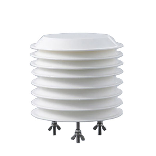
- Prefer integrated probes with radiation shields to avoid solar radiation-induced temperature measurement errors

Communication design for micro-meteorological monitoring systems must balance real-time performance, reliability, and compatibility. Typical architecture includes three layers:
- Modbus RTU over RS-485: Most mature industrial fieldbus solution, transmission distance up to 1200 m, supports multi-device daisy-chain connection
- SDI-12: Digital interface suitable for multi-parameter soil/hydrological monitoring, extremely low power, ideal for solar-powered scenarios
- Analog 4–20 mA: Backup communication method ensuring continuity of key parameters during digital communication failure
- IEC 61850: Power system standard protocol, suitable for seamless integration with substation automation systems
- MQTT over 4G/LoRa: Lightweight IoT protocol supporting reliable transmission in low-bandwidth environments
- OPC UA: Industry 4.0-oriented cross-platform interoperability protocol, suitable for complex multi-vendor device integration scenarios
- Supports RESTful API data push, facilitating integration with third-party O&M management platforms and digital twin systems
- Provides JSON/XML format historical data export interfaces to meet engineering audit and scientific research analysis needs
- Solar + battery independent power supply: Suitable for remote transmission line monitoring points without grid access; local irradiation and equipment power consumption must be calculated to ensure redundancy during continuous rainy weather
- Grid power access: Highest reliability; requires lightning surge protection and uninterruptible power supply (UPS) configuration
- Anemometer installation height typically 10 m (per WMO standard); ensure no obstructions within a radius of 10× installation height
- Bracket material: hot-dip galvanized steel or 304 stainless steel
- Equipment enclosure protection rating ≥ IP65, with active heat dissipation, suitable for wide temperature range –30℃ to +60℃

Phenomenon Description: Coexistence of multiple protocols (Modbus RTU, IEC 61850, proprietary) on site makes data aggregation difficult.
Solution: Deploy multi-protocol edge gateways (e.g., NiuBoL NB-IoT Gateway series) with built-in protocol conversion engine to uniformly map different protocol data to standard MQTT or OPC UA format, reducing complexity of upper-layer platform development.
Phenomenon Description: Strong electromagnetic environment around high-voltage transmission lines causes sensor signal interference, manifesting as periodic jumps in wind speed/temperature data.
Solution:
- Use twisted shielded cables for sensors, single-ended grounding of shield layer
- Install 120 Ω terminating resistor at RS-485 bus end to suppress signal reflection
- Add signal isolators on critical analog channels to achieve ground loop isolation
Phenomenon Description: High UV radiation and large diurnal temperature variation in high-altitude areas cause shell aging and seal failure.
Solution:
- Use UV-resistant modified polycarbonate or aluminum alloy shells with fluorocarbon coating
- Select aviation-grade waterproof connectors (IP67 or higher)
- Adopt double O-ring sealing at critical positions with periodic airtightness testing
NiuBoL micro-meteorological monitoring product line covers the full spectrum from standard environmental monitoring stations to high-voltage transmission dedicated devices, supporting deep customization of communication protocols, power supply schemes, and installation structures. Our technical support team provides integrators with full-process engineering support from solution design, equipment commissioning to platform integration, enabling efficient project delivery.
.jpg")
Q1: How to integrate micro-meteorological monitoring data with existing photovoltaic power station SCADA systems?
Standard solution accesses SCADA front-end processor via Modbus TCP/IP or IEC 61850 protocol and maps data to the SCADA real-time database. NiuBoL supports fast device registration and variable binding for mainstream SCADA platforms (e.g., KingSCADA, ForceControl, Wonderware).
Q2: What is the upper measurement limit of ultrasonic anemometers under strong wind conditions?
Conventional models can measure up to 60 m/s (equivalent to Beaufort scale 17 super typhoon), meeting most application scenarios except extreme high-wind zones.
Q3: Which cloud platform access protocols does the system support?
Natively supports MQTT v3.1/v5.0, HTTP, and other mainstream cloud platform protocol stacks. Protocol conversion gateways are available for private cloud platforms.
Q4: How can multiple micro-meteorological stations form a regional monitoring network?
Data aggregation across multiple sites is achieved via LoRa ad-hoc network or 4G; a single gateway can manage 32+ monitoring nodes. Network supports star, chain, and mesh hybrid topologies to adapt to complex terrain communication coverage requirements.
Q5: Recommended maintenance cycle in strong dust environments such as Gobi Desert?
Ultrasonic anemometers: quarterly surface cleaning, with focus on checking ultrasonic probe deposits; temperature & humidity sensors: replace dust filter cotton every six months. System supports remote sensor status diagnosis and dynamic adjustment of maintenance plans based on pollution index.
Q6: Can technical specification documents and performance proofs be provided during project bidding?
Yes. Standard bidding document templates compliant with technical specifications can be provided, including detailed technical parameter response tables, type test reports, and ISO 9001 system certificates. For overseas projects, ROHS compliance declarations and CE certification documents are available.

The value realization of transmission line micro-meteorological monitoring systems depends on full-chain technical synergy from sensor accuracy, communication reliability to platform intelligence. For system integrators, selecting equipment suppliers with deep customization capability and proven engineering service experience is the key decision to ensure project technical advancement and delivery reliability.
NiuBoL is committed to serving as a technical extension of our partners, reducing technical uncertainty and implementation risk in project delivery through modular hardware architecture, open software interfaces, and standardized engineering services. In the context of intelligent upgrading of new power systems, micro-meteorological monitoring is evolving from an auxiliary monitoring tool to core infrastructure. We look forward to working together with industry partners to advance technological progress and standard improvement.
 NBL-W-21GUWS-Ultrasonic-Wind-speed-and-direction-Sensor.pdf
NBL-W-61MUWS-Ultrasonic-Weather-Station-Instruction-Manual.pdf
NBL-W-71MUWS-Micrometeorological-Sensor-Operating-Instructions.pdf
Prev:Core Applications of Solar Power Environmental Monitor and Distributed Photovoltaic Weather Station
Next:Farm Weather Station: Precise Data Core Solution for Smart Agriculture Integration Projects
Related recommendations
Sensors & Weather Stations Catalog
Agriculture Sensors and Weather Stations Catalog-NiuBoL.pdf
Weather Stations Catalog-NiuBoL.pdf
Agriculture Sensors Catalog-NiuBoL.pdf
Water Quality Sensor Catalog-NiuBoL.pdf
Related products
 Combined air temperature and relative humidity sensor
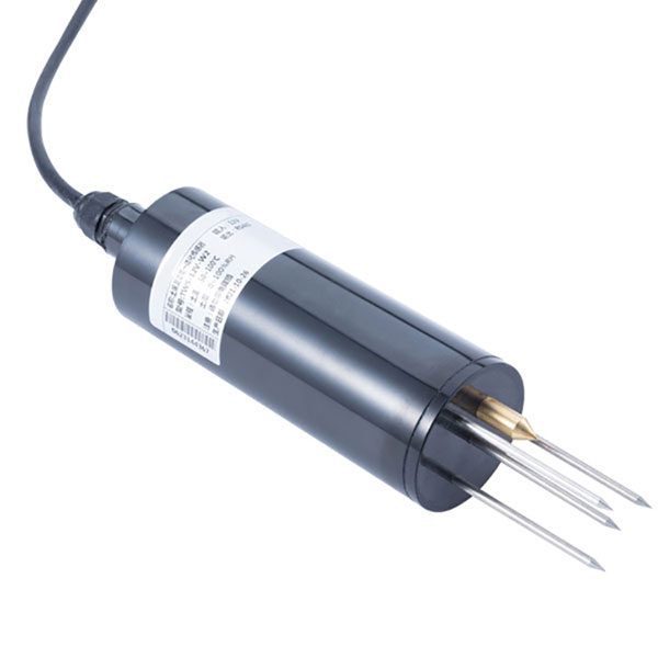 Soil Moisture Temperature sensor for irrigation|NBL-S-THR
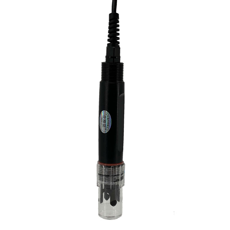 Soil pH sensor RS485 soil Testing instrument soil ph meter for agriculture |NBL-S-PH
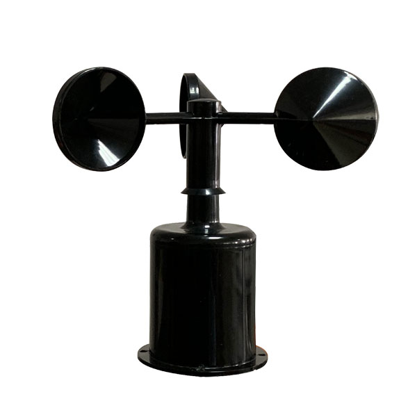 Wind Speed sensor Output Modbus/RS485/Analog/0-5V/4-20mA
 Tipping bucket rain gauge for weather monitoring auto rainfall sensor RS485/Outdoor/stainless steel
 Pyranometer Solar Radiation Sensor 4-20mA/RS485

Screenshot, WhatsApp to identify the QR code
WhatsApp number:+8615367865107
(Click on WhatsApp to copy and add friends)
