





— Blogs —
—Products—
 Consumer hotline +8618073152920
WhatsApp:+8615367865107
Address:Room 102, District D, Houhu Industrial Park, Yuelu District, Changsha City, Hunan Province, China
Product knowledge
Time:2026-01-22 10:32:42 Popularity:759
An automatic groundwater level monitor should deliver a comparable water-level record over time, not just a pressure reading from a probe in a well. The decisive project details are the reference elevation, the installed probe depth, the well's lowest expected water level, the selected output and the way a technician will service the cable. NiuBoL offers submersible level transmitters in different electrical configurations. A buyer should select a particular model and range after defining the well, rather than assuming that every pictured transmitter has the same interface or can be dropped to the bottom of any borehole.
A hydrostatic transmitter measures pressure from the water column above its sensing diaphragm. The controller converts that pressure to a height using the configured density and then relates it to a reference, such as a surveyed measuring point at the wellhead. If one reporting system displays depth below wellhead and another displays elevation above a project datum, they can show different numbers for the same water surface. Specify the required sign convention and units in the point list.
Measure total well depth, screened interval, seasonal high and low water levels, and available clearance for the probe. Leave the sensing head below the lowest water level that must be measured, but above sediment and any pump intake turbulence that would compromise the reading. A range selected merely from total borehole depth may waste useful resolution; a probe placed too high can leave the water during dry periods. Record the installed probe reference depth and cable marks so that a future replacement can be returned to a comparable position.
The physical relation is pressure = density × gravitational acceleration × water height. A controller that assumes freshwater density is making a reasonable engineering approximation only when the medium matches that assumption and the required accuracy permits it. Saline, warm or chemically unusual water can change the conversion. If the project needs an elevation trace across multiple wells, also survey each measuring point to one common datum; assigning every well an arbitrary local zero prevents reliable comparison between locations.
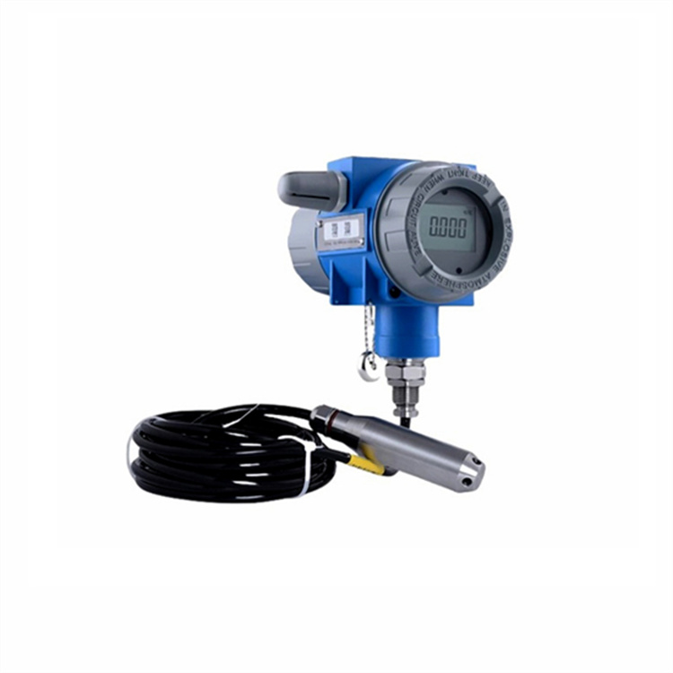
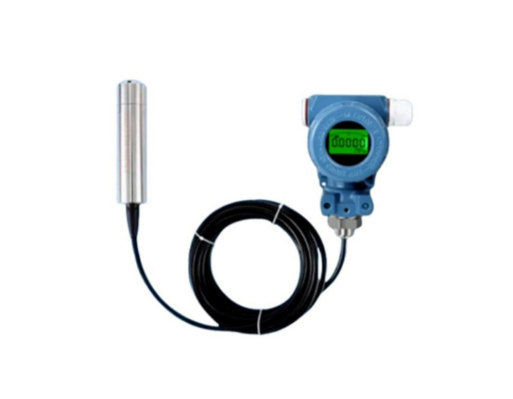
The first image shows a split-type transmitter with a separate display. That arrangement is useful where a local reading is needed, but the display housing needs a suitable, accessible mount. The probe, display and logger are distinct items in the order. Their combined price and field work should be compared with an integrated sensor only after the required maintenance and data access are clear.

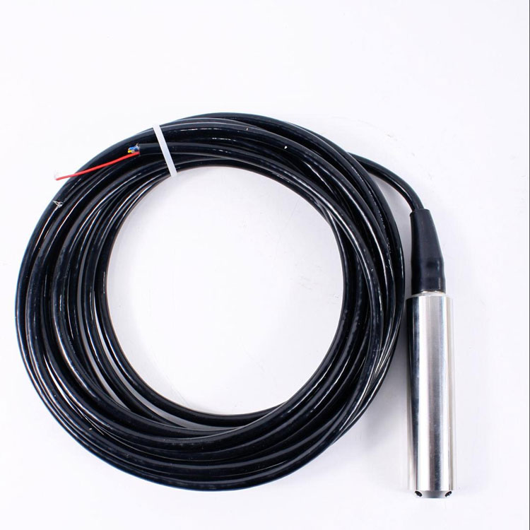
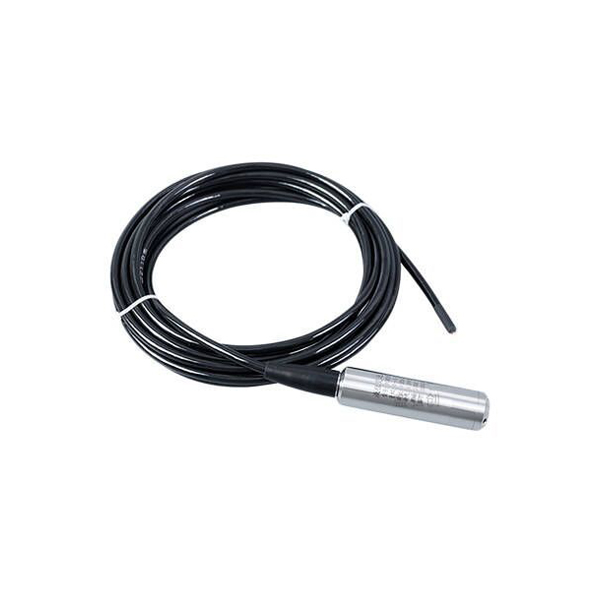
The product photographs show several NiuBoL level variants. The NBL-L-SMP4603 product page describes 4-20 mA and voltage configurations and says to select another series when RS485 Modbus RTU is required. The NBL-L-SMP4631 split-type series lists RS485 Modbus, HART and 4-20 mA as output options. These are not interchangeable terminals on every shipped unit; confirm the ordered suffix, wiring drawing, supply and register map or loop span before issuing a purchase order.
A 4-20 mA loop may fit an existing RTU with an analog input. Its engineering scale must be documented: which current corresponds to which water-column height, and how the RTU flags an open circuit or out-of-range value. RS485 Modbus RTU can simplify a multi-point digital integration, but it still requires a compatible master, addresses, cable design and confirmed register interpretation. A wireless transmitter or cellular gateway is another system layer, not an intrinsic property of a submersible pressure probe.
| Project requirement | Decision to make | Handover evidence |
|---|---|---|
| Level referenced to a borehole | Depth below measuring point or elevation above datum | Surveyed point, probe depth and conversion formula |
| Existing analog RTU | 4-20 mA model, loop supply and scale | Wiring, current check and fault state |
| Digital polling | Ordered RS485 Modbus RTU variant | Address, register, unit and polling test |
| Remote unattended site | Logger, power, modem and data service | Outage and recovery test |
Do not infer a 400 m well capability or a fixed 2 km communications reach from a general article. Probe pressure range, cable length, power and bus performance depend on the exact product variant and installed design. Request the datasheet for the quoted configuration.

For a vented gauge-pressure transmitter, the vent tube in the cable provides atmospheric reference. Keep its termination dry, open to air as instructed and above flooding risk. Crushing or sealing the tube can introduce barometric error. The wellhead cable must be supported so the probe is not carried by an unsuitable connector, and the installation should avoid sharp bends, pump abrasion and damage during well access. Check the sensor body's material against the measured water, especially where salinity or industrial contamination is possible.
Some wells contain sediment, iron deposits or biological growth. These may obstruct the pressure port, even when the housing itself is intact. Plan a retrieval method and a cleaning record. A protected probe can be more serviceable than a probe wedged into a narrow screen; choose the placement with both measurement and recovery in mind. Where pumping causes rapid drawdown, decide whether the project wants static groundwater level, pumping level or both, and log pump state with the data.
At an observation well, leave enough cable slack for thermal movement and future access, but do not allow a loose coil to catch the pump or well screen. At a municipal well with frequent service, identify the cable before contractors pull the pump. A sealed wellhead should still provide a dry location for vent termination or a suitable pressure-reference arrangement for the ordered probe. The contractor should document how the cable enters the enclosure, how strain is relieved and how a technician can retrieve the sensor without cutting a permanent splice.
Wireless display units in the photographs illustrate a possible remote-reading architecture. They do not prove that every submersible probe communicates directly with a mobile platform. The wellhead transmitter, local logger, modem and receiving application need separate power, configuration and ownership decisions.
At installation, measure water depth with a maintained manual dip meter at the defined reference point. Record the time, probe depth, controller output, manual reading and any correction applied. Repeat after the well settles from installation disturbance. A single comparison can establish the wiring and datum, but it cannot characterize seasonal drift. Set a follow-up comparison interval according to the monitoring program and the consequences of an erroneous trend.
Check the complete data path from sensor to PLC or RTU and then to the database: unit, timestamp, well ID, sign convention and the alarm or missing-data code. Simulate a disconnected sensor under controlled conditions. The system must not report a plausible groundwater level when a loop is open or the Modbus poll has failed. If local storage is required during a communications outage, specify and test the actual logger behavior.
A long-term record also needs event metadata. Note pumping tests, well rehabilitation, probe cleaning, cable replacement, reference-point changes and nearby construction. Without those annotations, a step in the time series may look like a hydrological change when it is really a changed installation.
For a regional observation network, consistency between wells matters more than an elaborate feature set at one location. Use the same level convention, time base and maintenance record throughout. For a mine-dewatering site, record pump operation and choose sampling fast enough to capture the intended drawdown event. For a water-supply well, plan service around pumping schedules and protect the cable from routine well work. Geothermal or contaminated sites require an explicit media and temperature compatibility check before a standard groundwater transmitter is offered.
The price comparison should separate probe variant, range, cable length, display, logger, communication module, battery or mains supply, wellhead hardware, installation and commissioning. A low probe price is not the installed system cost. Give NiuBoL the well construction, water chemistry if known, minimum and maximum level, required output, cable route and the existing PLC or RTU interface to obtain a model-specific quotation.
No. The transmitter observes pressure corresponding to water above its diaphragm. The system needs the probe's reference elevation or depth and an agreed conversion to report groundwater level.
That is generally a poor default. Sediment can cover the port, and pump intake or cleaning work can damage the head. Set the probe below the lowest level of interest but clear of known obstructions and record its position.
No. Some are 4-20 mA or voltage variants. Confirm the exact model and ordered output. A digital network also needs a logger or PLC master and a register map.
On a vented gauge-pressure model it provides an atmospheric reference. A flooded, blocked or crushed vent can change the indicated level without any change in the well water.
Compare the live sensor reading with a manual depth measurement at the same marked point and time. Verify the converted datum, unit, timestamp, well ID and response to a disconnected sensor.
Provide well depth and diameter, expected level range, reference elevation, water chemistry, cable length, power, existing input type and remote data requirement. The output option and installation hardware can then be priced without assuming one universal sensor.
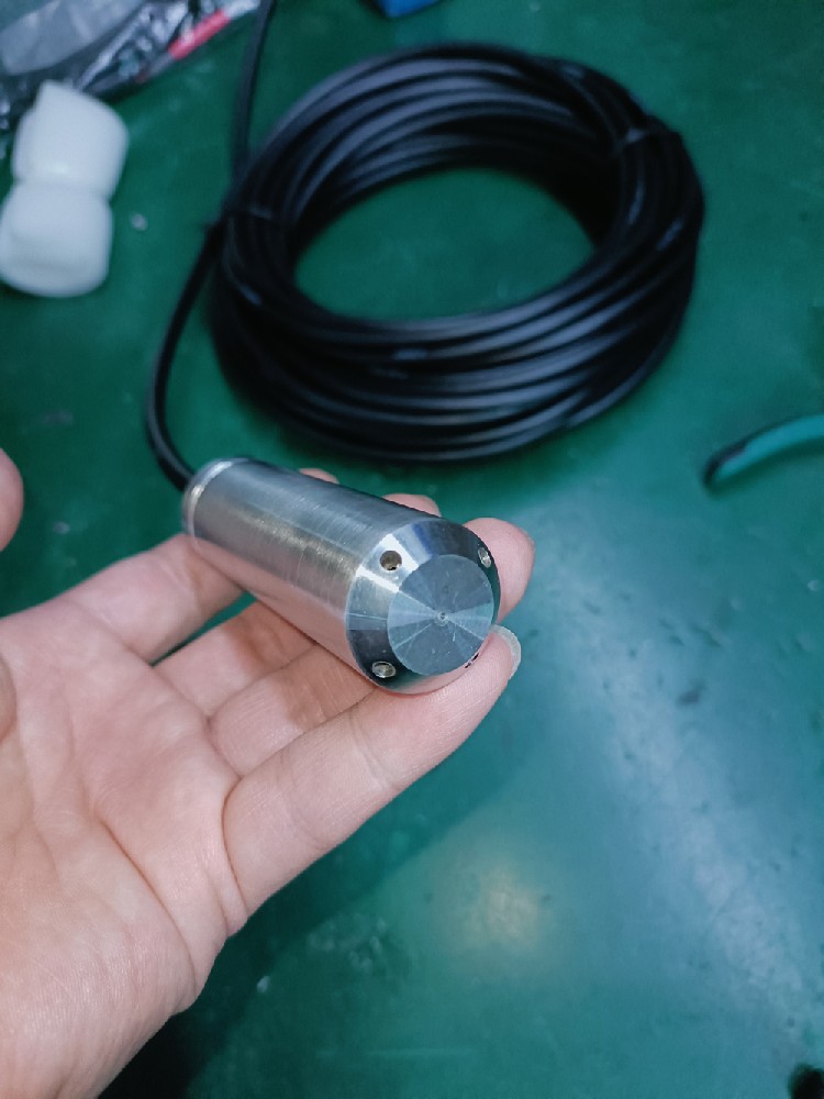
An automatic groundwater level monitor is a measurement chain: submerged pressure probe, known reference, compatible acquisition input and a maintained record. NiuBoL offers several transmitter forms; select one by well geometry and interface, then verify the reported level against a manual reading before using the trend for water-resource decisions.
Prev:Open Channel Flow Monitoring System: Verify Area and Velocity
Next:Online Water Quality Sensors: Chlorine, Turbidity and COD Signal Interpretation
Related recommendations
Sensors & Weather Stations Catalog
 Agriculture Sensors and Weather Stations Catalog-NiuBoL.pdf
Weather Stations Catalog-NiuBoL.pdf
Agriculture Sensors Catalog-NiuBoL.pdf
Water Quality Sensor Catalog-NiuBoL.pdf
Related products
 Combined air temperature and relative humidity sensor
 TDR Soil Moisture & Temperature Sensor for irrigation| RS485 |4-20mA| NBL-S-THR
 Soil pH sensor RS485 soil Testing instrument soil ph meter for agriculture |NBL-S-PH
 Wind Speed sensor Output Modbus/RS485/Analog/0-5V/4-20mA
 Tipping bucket rain gauge for weather monitoring auto rainfall sensor RS485/Outdoor/stainless steel
 Pyranometer Solar Radiation Sensor 4-20mA/RS485


Screenshot, WhatsApp to identify the QR code
WhatsApp number:+8615367865107
(Click on WhatsApp to copy and add friends)

