

— Blogs —
—Products—
 Consumer hotline +8618073152920
WhatsApp:+8615367865107
Address:Room 102, District D, Houhu Industrial Park, Yuelu District, Changsha City, Hunan Province, China
Product knowledge
Time:2026-11-07 15:52:33 Popularity:5
A soil moisture sensor reports volumetric water content (VWC) as a percentage by measuring the dielectric permittivity of the soil around its electrodes. Getting a useful number depends less on the sensor's advertised accuracy than on where the probe sits, how well it contacts the soil, and whether the reading is interpreted together with temperature and electrical conductivity. Installed badly, a ±3% sensor can be wrong by far more than 3%.
Most capacitance and FDR probes respond to the apparent dielectric constant of the surrounding medium. Water has a dielectric constant near 80, dry soil solids around 3–5, and air about 1, so a change in water content produces a large, measurable change in capacitance. The instrument converts that into a VWC percentage using a calibration function. That function is soil-specific: the same dielectric reading in a sandy loam and in a high-clay, high-organic soil does not correspond to the same VWC.
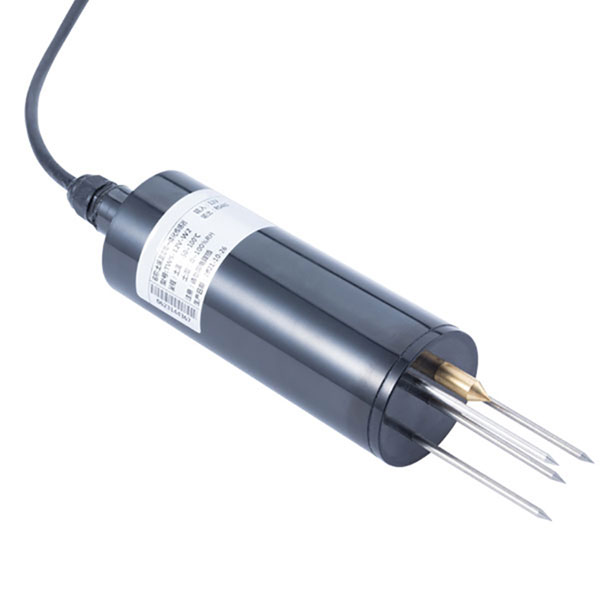
Figure 1. TDR Soil Moisture & Temperature Sensor for irrigation — RS485 — 4-20mA — NBL-S-THR.
VWC is not the same as plant-available water, and it is not a direct irrigation command. A clay soil at 30% VWC may hold water at a tension that roots cannot easily extract, while a sand at 12% VWC may be near field capacity. The number that matters agronomically is the distance between the current reading and the site's own thresholds, established by observing when the crop actually shows stress.
Combined sensors add useful context. The NiuBoL NBL-S-TMC is a three-in-one probe that measures soil temperature, soil moisture and electrical conductivity in one IP68 housing and transmits over RS485 Modbus RTU. It includes built-in EC temperature compensation across a 0–50°C compensation range, because conductivity changes with temperature even when the dissolved salt content does not. For nutrient-solution work, the manufacturer specifies checking that expected conductivity stays within 0–10000 μS/cm and that installation, cleaning and measurement conditions suit continuous use.
| Parameter | Value | Unit / condition | Source |
|---|---|---|---|
| Soil moisture range | 0–100 | % (VWC) | NBL-S-THR, NiuBoL product page |
| Soil temperature range | −50 to 100 | °C | NBL-S-THR, NiuBoL product page |
| Moisture resolution | 0.1 | % | NBL-S-THR |
| Temperature resolution | 0.1 | °C | NBL-S-THR |
| Moisture accuracy | ±3 | % | NBL-S-THR |
| Temperature accuracy | ±0.5 | °C | NBL-S-THR |
| Supply | DC 12–24 | V | NBL-S-THR |
| EC range | 0–15 | mS/cm | soil EC sensor page |
| EC resolution | 0.01 | mS/cm | soil EC sensor page |
| Salinity range | 0–8000 | mg/L | soil EC sensor page |
| Salinity resolution | 1 | mg/L | soil EC sensor page |
| pH range | 0–14 | pH | soil pH sensor page |
| Outputs | RS485 Modbus, 4–20 mA, 0–5 V | interface options | NiuBoL sensor pages |
| EC temperature compensation | 0–50 | °C | NBL-S-TMC |
| Ingress protection | IP68 | probe housing | NBL-S-TMC |
One NiuBoL page states that when volumetric soil moisture is above approximately 20%, dissolved ions form a more continuous conductive pathway and EC readings become more representative of soluble salt content. The same page explicitly warns that the 20% figure is a measurement reference, not a universal irrigation threshold. That distinction is worth keeping: a VWC-based irrigation trigger and an EC validity condition are two different things, and conflating them produces bad agronomy and bad data at the same time.
Depth. Place the sensing volume in the active root zone, not at the surface. A single shallow probe mostly reports evaporation and irrigation wetting fronts, not what the roots see. For row crops with a root zone spanning 0–40 cm, two depths (for example 15 cm and 35 cm) reveal whether water is reaching the lower layer or merely wetting the top.
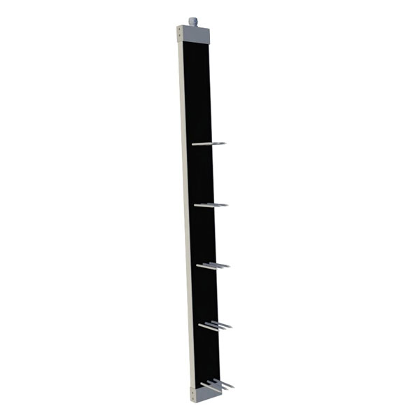
Figure 2. NBL-S-TM-MD Multi-Layer Soil Moisture Temperature Salinity Sensor — RS485 Modbus.
Contact. Air gaps around the electrodes are the dominant installation fault. Backfill with a slurry of native soil and water, tamp gently, and avoid creating a preferential flow path down the cable trench. A probe installed in a hole that is too wide will read the water that runs down the hole rather than the surrounding soil.
Distance from the emitter. Too close and the sensor responds to a single drip line rather than the field; too far and it misses irrigation events entirely. Record the horizontal distance from the emitter as a commissioning value, because it changes how every subsequent reading is interpreted.
Representativeness. Slopes, compacted headlands, wheel tracks and soil texture transitions each produce their own moisture regime. One probe cannot characterize a variable field. Use at least one probe per management zone, defined by soil texture and irrigation schedule.
Cable and power. RS485 A/B should be twisted pair, with the shield terminated at one deliberate earth point. Keep the sensor cable away from solenoid valve wiring, and remember that an RS485 soil sensor does not supply the power or switching function needed to drive a solenoid — that requires a separate controller or relay output.
An RS485 Modbus RTU sensor is a digital field device, not a standalone remote station. Individual RS485 sensors do not need their own cellular modem; remote communication is normally handled by the data logger or IoT gateway they connect to. The logger polls registers, timestamps the values, stores them locally and forwards them over 4G, Ethernet or whatever uplink the site has. That split has a practical consequence: if the uplink fails, a logger with local storage and resume capability preserves the series, while a sensor directly polled by a cloud service loses it.
NiuBoL's industrial collector specification describes 16 sensor inputs, 128 GB storage and breakpoint resume transmission, with remote configuration of sampling frequency and thresholds. Those capabilities matter more for irrigation decisions than the sensor's resolution does, because an irrigation controller reacts to trends over hours, not to a single sample. When designing the register map, log the raw VWC word alongside temperature and EC, plus a quality or status flag if the device provides one. Never log only a smoothed or averaged value: smoothing hides exactly the wetting-front events you need to see.
Output choice depends on the receiving system. RS485 Modbus RTU preserves the full value and supports multiple devices on one bus; 4–20 mA is robust for a single long analogue run into a PLC but loses diagnostics; 0–5 V suits short laboratory-style wiring. NiuBoL offers all three on several soil sensor variants.
The following is an illustrative calculation, not a NiuBoL project dataset. Assume a loam block with two probes per management zone at 15 cm and 35 cm. At 06:00 the shallow probe reads 22.0% VWC and the deep probe 24.5% VWC. The site's own observed refill point is 18.0% VWC at 15 cm, established over a season by comparing probe readings with crop response. A drip line delivers 4.0 mm/h over the wetted area, and the previous irrigation event raised shallow VWC by 6.0 percentage points in 1.5 hours, implying an effective storage response of 4.0 percentage points per hour of operation under those soil and flow conditions.

Figure 3. Soil Moisture Temperature sensor.
To raise the shallow layer from 18.0% back to 24.0% requires 6.0 percentage points, or 1.5 hours of irrigation. But the deep probe is already at 24.5%, so a full 1.5 hours risks pushing water below the root zone. A defensible schedule is a 0.75-hour pulse, followed by a 2-hour redistribution pause, then a second 0.75-hour pulse if the shallow probe has not reached 23.0%. The two pulse readings also give a direct check on infiltration: if the shallow probe barely moves during the pause while the deep probe rises, water is bypassing the intended layer — most likely through a preferential path such as the cable trench.
Now add EC. If the EC channel reports a rising trend while VWC falls, salinity is concentrating in the remaining soil water, which is a normal drying pattern. If EC rises sharply immediately after an irrigation pulse with a fertigation injection, the injection ratio or mixing is wrong. Because EC is temperature compensated over 0–50°C on the NBL-S-TMC, a drift that persists after correcting for temperature is more likely to be a real change in soluble salts than a thermal artefact. Above roughly 20% VWC the EC channel is more representative of soluble salt content; below that, treat EC trends as qualitative only.
Soil-specific calibration. A factory calibration in a generic mineral soil can be off by several percentage points in high-clay or high-organic-media soils. Run a gravimetric check at two moisture levels on the site's own soil.
Salinity and temperature extremes. High EC compresses the dielectric response and can bias VWC upward. Outside the 0–50°C EC compensation range, conductivity values should not be treated as compensated.
Contact loss after freeze–thaw or shrinkage. Clay soils shrink away from the probe in dry periods, creating an air gap that reads as a sudden drop in moisture. Watch for step changes that do not coincide with irrigation or rain.
Preferential flow. Cable trenches, cracks and worm channels deliver water straight past the sensing volume. A probe that shows no wetting front after an irrigation event is often correctly reporting a bypassed volume.
Power and bus faults. Insufficient supply at the end of a long RS485 run produces intermittent dropouts that look like sensor drift. Measure voltage at the probe, not only at the panel.
Confusing VWC with availability. A correct VWC number can still lead to over-irrigation if the site's refill point was never calibrated. The threshold, not the sensor, usually decides whether the irrigation decision is right.
Q1. Is 20% VWC a good irrigation trigger?
No. NiuBoL's own documentation describes ~20% as the point above which EC readings become more representative of soluble salts — a measurement reference, not an irrigation threshold. Establish your own refill point from local soil and crop response.
Q2. Can one RS485 soil sensor run a solenoid valve?
No. An RS485 sensor provides measurement only; driving a solenoid needs a controller with a rated output. Keep valve wiring separate from the sensor bus.
Q3. How many probes does a variable field need?
At least one per management zone, ideally at two depths. Zones should be defined by soil texture, slope and irrigation schedule.
Q4. Why does EC rise when the soil dries?
As water is removed, dissolved salts concentrate in the remaining solution. Temperature compensation removes the thermal component, so a persistent rise usually reflects real salinity change.
Q5. Which output should I use for a multi-probe site?
RS485 Modbus RTU, because several sensors share one bus and the raw values and diagnostics are preserved. Use 4–20 mA for a single long analogue run to a PLC.
Q6. How do I verify the sensor after installation?
Compare against gravimetric samples at two moisture levels, confirm supply voltage at the probe, and check that a wetting front appears at both depths in the expected order after an irrigation event.
Prev:Negative Ion Monitors: What They Measure, How They Work and Where Readings Go Wrong
Next:Installing a Monitoring System: Siting, Wiring, Commissioning and the Mistakes That Bias Data
Related recommendations
Sensors & Weather Stations Catalog
 Agriculture Sensors and Weather Stations Catalog-NiuBoL.pdf
Weather Stations Catalog-NiuBoL.pdf
Agriculture Sensors Catalog-NiuBoL.pdf
Water Quality Sensor Catalog-NiuBoL.pdf
Related products
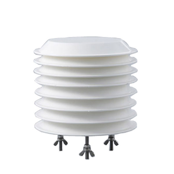 Combined air temperature and relative humidity sensor TDR Soil Moisture & Temperature Sensor for irrigation| RS485 |4-20mA| NBL-S-THR
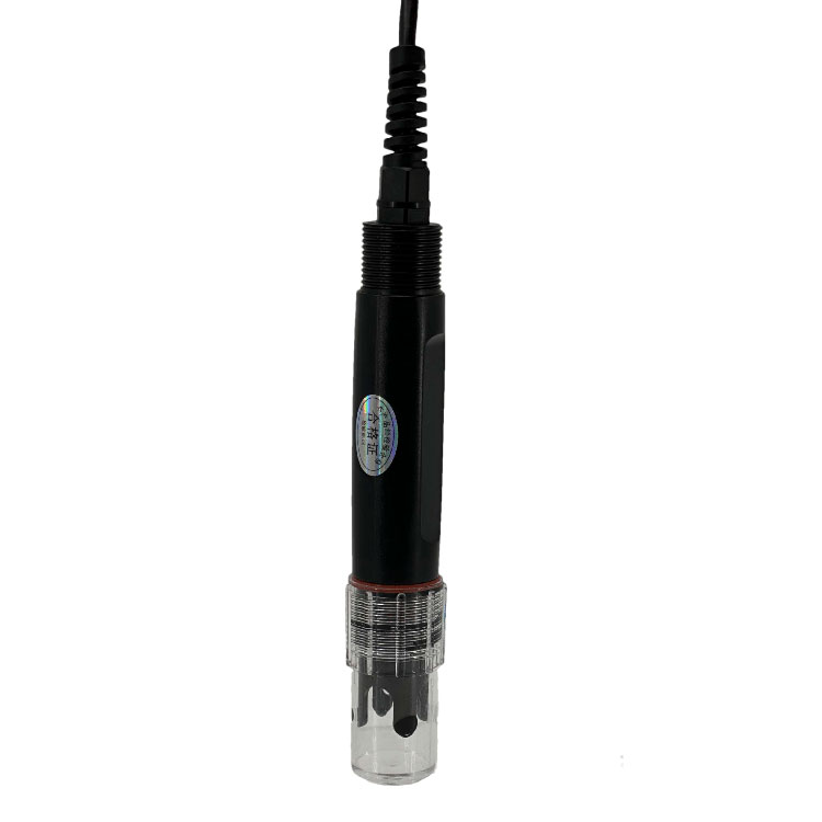 Soil pH sensor RS485 soil Testing instrument soil ph meter for agriculture |NBL-S-PH
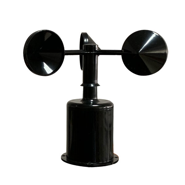 Wind Speed sensor Output Modbus/RS485/Analog/0-5V/4-20mA
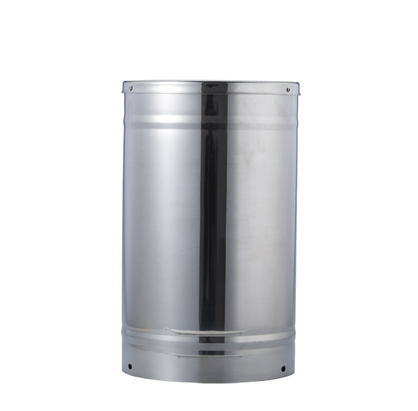 Tipping bucket rain gauge for weather monitoring auto rainfall sensor RS485/Outdoor/stainless steel
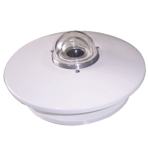 Pyranometer Solar Radiation Sensor 4-20mA/RS485


Screenshot, WhatsApp to identify the QR code
WhatsApp number:+8615367865107
(Click on WhatsApp to copy and add friends)