





— Blogs —
—Products—
 Consumer hotline +8618073152920
WhatsApp:+8615367865107
Address:Room 102, District D, Houhu Industrial Park, Yuelu District, Changsha City, Hunan Province, China
Product knowledge
Time:2026-01-23 10:26:35 Popularity:1062
An automatic water level and rainfall monitoring system combines water level sensors, rain gauges, data loggers, communication equipment and a monitoring platform to collect hydrological information continuously. Such systems are used in rivers, reservoirs, irrigation channels, flood monitoring networks, urban drainage and water-resource management. To interpret the two measurements together, the station needs a stable water-level reference and timestamps that describe when each observation was made.
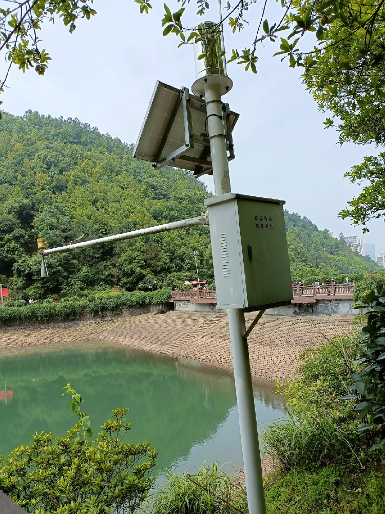
A typical monitoring station uses a non-contact radar water level sensor to measure changes in water surface elevation and a tipping bucket rain gauge to record precipitation. The measurements are collected by a compatible RTU or data logger and can be transmitted through 4G, Ethernet or other supported communication networks.
For remote installations, the system can also include solar power, battery storage, mounting structures, lightning protection and local data storage. The complete configuration depends on measurement requirements, installation conditions and communication availability.
Water level and rainfall provide complementary information about local hydrological conditions. Rainfall instruments measure precipitation received at a monitoring site, while water level sensors record changes in rivers, reservoirs, drainage channels or other water bodies.
| Parameter | Instrument | Monitoring Purpose |
|---|---|---|
| Water Level | Radar Water Level Sensor | Monitor changes in river, reservoir or channel water level |
| Accumulated Rainfall | Tipping Bucket Rain Gauge | Measure total rainfall during selected time periods |
| Rainfall Intensity | Rain Gauge + Data Processing | Calculate precipitation rate over a defined interval |
| Water Velocity | Optional Velocity Sensor | Monitor water movement in rivers and channels |
| Flow Rate | Optional Flow Monitoring System | Estimate or measure discharge using suitable velocity and cross-sectional information |
Water level, rainfall, velocity and flow rate are different measurement parameters. A radar water level sensor does not independently measure rainfall or water velocity. Additional instruments are required when these parameters must be monitored together.
A complete hydrological monitoring station consists of measurement instruments, data acquisition equipment, power supply, communication devices and supporting structures.
| System Component | Function |
|---|---|
| Radar Water Level Sensor | Measures distance to the water surface for continuous water level monitoring |
| Tipping Bucket Rain Gauge | Measures accumulated liquid precipitation |
| RTU / Data Logger | Collects, timestamps, processes and stores measurement data |
| Communication Equipment | Transmits collected data through 4G, Ethernet or a compatible wireless network |
| Solar Power System | Provides electrical power using a solar panel, charge controller and battery |
| Mounting Structure | Supports sensors, solar panels, data enclosures and communication antennas |
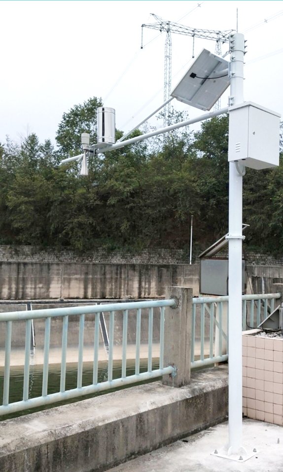
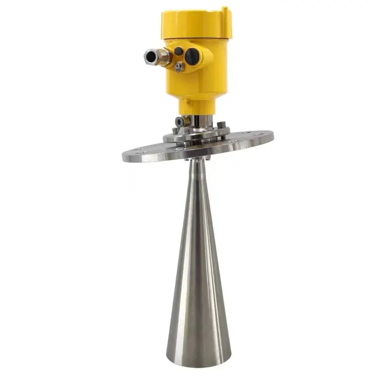
A radar water level sensor measures the distance between its antenna reference and the water surface. It is normally mounted above the water on a bridge, cross arm, support pole or other stable structure. Once the reference elevation is surveyed, water-surface elevation is calculated by subtracting the measured distance.
For example, with the antenna reference at elevation 102.400 m and a measured distance of 3.150 m, the water-surface elevation is 99.250 m. A later distance of 2.950 m represents a 0.200 m rise. These are illustrative values. They require a common surveyed datum and the instrument's correct measurement reference; a distance reading by itself is not an elevation.
If a bracket moves, the data may shift even though the water has not. Establish a fixed survey mark independent of the mounting arm, and recheck the antenna elevation after structural work or replacement. Preserve the time of any datum correction so that an apparent jump is not mistaken for a hydrological event.
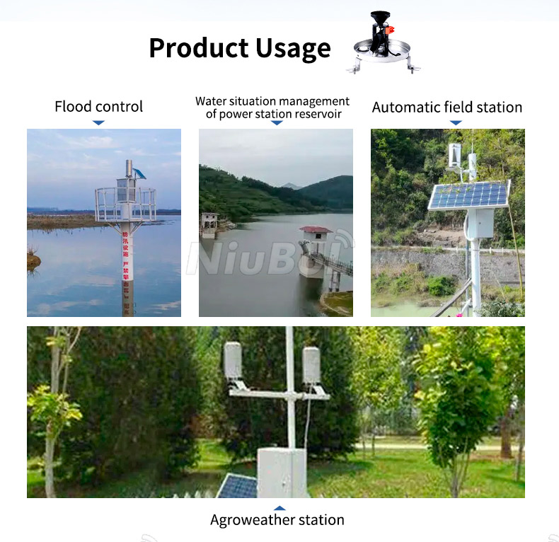
NiuBoL radar level instruments are available in different configurations. For the current 77-79 GHz configuration, use the limits below together rather than combining its beam angle or power rating with a different radar version. The illustrated field arrangements are installation examples, not proof that every pictured sensor shares these specifications.
| 77-79 GHz radar parameter | Specified value | Installation consequence |
|---|---|---|
| Distance range | 0.1-65 m; approximately 0.1 m blind zone | Keep the highest expected water surface outside the near-field limit. |
| Resolution and accuracy | +/-1 mm under specified measurement conditions | Do not treat the test-condition figure as guaranteed station accuracy at every range. |
| Beam angle | 6 degrees | Check the beam footprint at the lowest water level, when the measuring distance is greatest. |
| Supply and maximum load | 10-30 V DC; less than 0.2 W | Add logger, modem and other loads separately for solar sizing. |
| Interface and protection | RS485 Modbus RTU; IP67 | Use a compatible acquisition port and keep the installation above flood exposure. |
For a 6-degree full beam angle, the approximate footprint diameter at 10 m distance is 2 x 10 x tan(3 degrees), or 1.05 m. This geometric check helps identify nearby piers or banks that might enter the path. It does not guarantee echo performance on a disturbed water surface. Keep the instrument perpendicular to the water and inspect the echo behavior at the actual site.
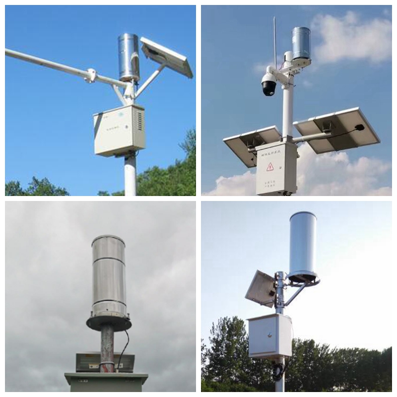
A tipping bucket rain gauge collects rainfall through a calibrated opening. Rainwater enters a mechanical tipping bucket assembly, and each completed tipping event represents a known increment of accumulated precipitation.
The NBL-W-RS Tipping Bucket Rain Gauge is a common option for automatic hydrological and weather monitoring stations.
For the NBL-W-RS configuration, the specified rainfall resolution is 0.2 mm, the collector diameter is approximately 200 mm, and the rainfall intensity range is 0–4 mm/min. The available output may be a switching or pulse signal, RS485 or another model-specific configuration.
A standard tipping bucket rain gauge is intended primarily for liquid precipitation. Snow and freezing conditions may require suitable heated or specialized precipitation measurement equipment.
For projects requiring a finer rainfall increment, the NBL-W-DRS Double Tipping Bucket Rain Gauge offers a separate 0.1 mm measurement configuration.
The rain gauge and radar do not need to occupy the same bracket. A bridge rail may suit a radar support but expose a collector to obstruction or splash. A rigid open rain-gauge position connected to the same logger can preserve timing without forcing both instruments into a compromised location.
The measurement instruments provide their local output signals to a compatible RTU, PLC or data logger. The receiving equipment collects the measurements, applies the required engineering-unit conversion and stores records with timestamps.
Radar Water Level Sensor + Rain Gauge → RS485 / Pulse → RTU / Data Logger → 4G / Ethernet → Monitoring Platform
A typical hydrological monitoring record may contain station ID, measurement timestamp, water level, accumulated rainfall, rainfall intensity and sensor or communication status.
Depending on the data logger configuration, measurements can be stored locally during a temporary network outage and transmitted after communication is restored. Local buffering, storage capacity and recovery behavior should be confirmed for the selected equipment.
Rainfall accumulated from 10:00 to 10:05 is an interval quantity. Water level measured at 10:05 is an observation at a particular time, unless the system explicitly reports an average. Store these distinctions rather than labeling both values simply as "10:05 data." A server receipt time is not an adequate replacement for the measurement time when transmission is delayed.
Choose acquisition and reporting intervals according to how quickly the site can change. A small urban drain may rise faster than a large reservoir. A five-minute reporting interval, for example, need not mean reading the level only once every five minutes. A logger can sample more frequently and transmit selected statistics, provided the stored minimum, maximum, average and end value are clearly identified.
Rain recorded at a station is not necessarily the rain that caused its observed level rise. Upstream rainfall, gate movements, pumping and tidal influence can alter the response. Nor does 12 mm of rainfall imply a 12 mm water-level increase: contributing area, storage, infiltration and discharge determine the relationship. For catchment interpretation, assess whether one rain gauge represents the contributing area.
Test the clock after a restart and after a communication outage. Backfilled records should retain their original measurement times and should not appear as a new storm at the moment of upload. Keep missing observations distinct from zero rainfall and from a flat water level.
Remote hydrological monitoring stations are often installed where mains electricity is unavailable. A solar-powered configuration may include a photovoltaic panel, charge controller, rechargeable battery and low-power data acquisition equipment.
Solar panel and battery capacity should be selected according to the total equipment power consumption, local sunlight conditions, communication frequency and the required backup period.
Power consumption should be calculated for the complete station, including the radar sensor, rain gauge transmitter if powered, RTU, cellular modem and any additional equipment.
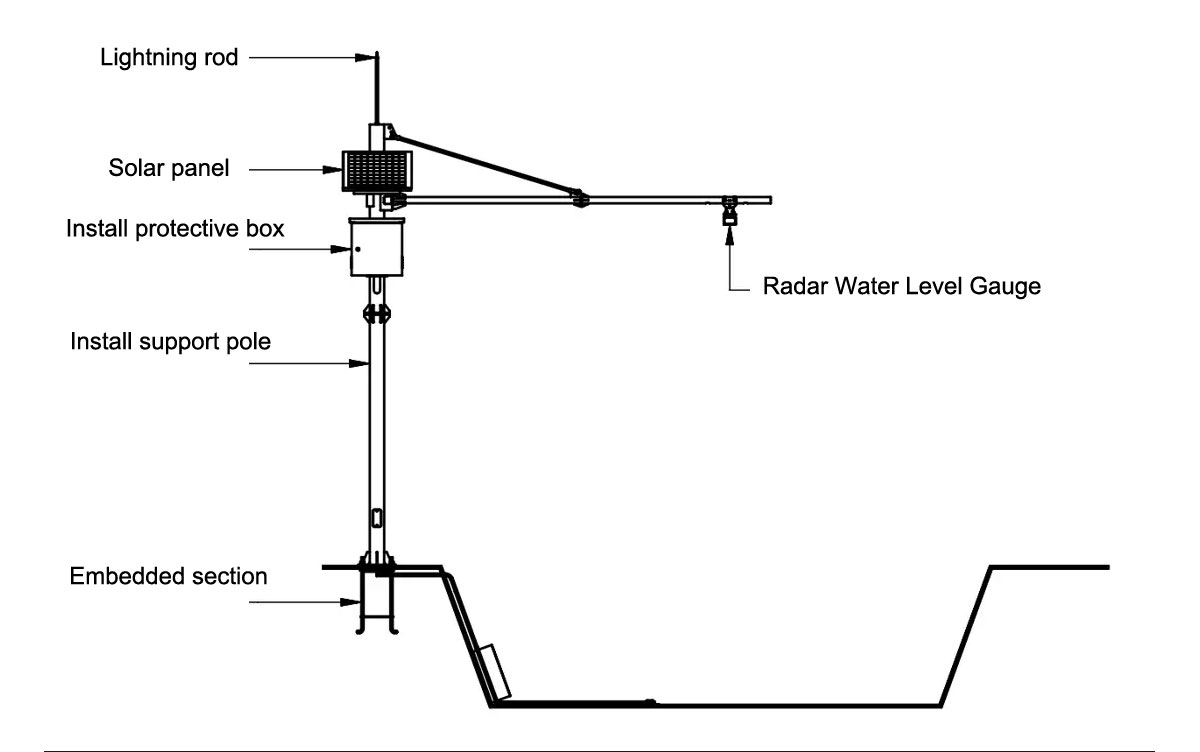
The two primary measurement instruments have different installation requirements. Radar water level sensors need an unobstructed measurement path toward the water surface, while rain gauges require a representative open location for precipitation collection.
| Installation Item | Requirement |
|---|---|
| Radar Mounting | Use a rigid support with a stable reference height above the water surface |
| Radar Beam | Avoid bridge structures, riverbanks, vegetation and other reflecting obstacles within the measurement path |
| Rain Gauge Location | Choose an open position away from major rainfall obstructions |
| Rain Gauge Leveling | Level the collector and verify the tipping bucket mechanism |
| Electrical Protection | Provide suitable grounding, surge protection and protected cable routing |
| Data Verification | Confirm correct engineering units, timestamps, sensor readings and communication status |
| Observed pattern | Possible explanation | Useful check |
|---|---|---|
| Level rises without local rain | Upstream runoff, gate operation or backwater; alternatively a datum or echo change | Compare upstream records and operating logs; check a staff gauge referenced to the same datum. |
| Rain is recorded but level remains flat | Little runoff, delayed response or a stale level channel | Check timestamps and direct sensor updates before concluding that the catchment did not respond. |
| Sudden level step after maintenance | Bracket elevation or configured offset changed | Resurvey the measurement reference and review the time of the intervention. |
| Rainfall appears as one large value after an outage | Accumulated total assigned to the reconnection time | Inspect locally stored intervals and the cumulative-counter handling. |
| Short level spikes near structures | Disturbed surface or intermittent unwanted echoes | Review the echo and mounting path alongside independent level observations. |
Rainfall and water level measurements can be analyzed together to assess how rivers, reservoirs and drainage systems respond to precipitation.
For example, a monitoring platform may compare rainfall accumulated over the previous hour with changes in river water level during the same period. This can support flood surveillance, watershed studies and the evaluation of local hydrological conditions.
However, rainfall and water level measurements alone do not automatically provide reliable flood predictions. Forecasting and early-warning systems require suitable hydrological models, monitoring coverage, historical data and independently defined warning procedures.
When the monitoring platform supports configurable thresholds and notifications, measured values can also be used to trigger alerts when predefined water level or rainfall limits are exceeded.
Yes, when the logger has the appropriate input and acquisition logic. A pulse-output gauge needs a compatible counter input; an RS485 gauge needs the correct Modbus RTU mapping and address. Match the actual output, not only the product name, and verify rainfall increments through the complete data path.
Check the shortest distance at maximum expected water level, the longest distance at minimum level and the beam clearance across that range. Also allow for flood exposure and structural access. A long maximum range does not compensate for a mounting position inside the near-field limit during a flood.
Not automatically. A rainfall threshold normally refers to an accumulation period, while a level threshold refers to a defined datum and may also consider rate of rise. Set each from the site's response and operating procedures. Pair the records for interpretation without treating the two quantities as interchangeable.
Only if the selected logger supports the required local acquisition and storage. Verify storage capacity, clock retention and recovery behavior with a deliberate connection interruption. Uploading a current value after reconnection does not demonstrate recovery of the missing intervals.
Preserve the surveyed water-level datum, units, timestamp convention and channel meaning. Recheck the new instrument's antenna reference, offset, Modbus registers and valid range. A replacement that outputs distance where the old channel expected water level can invert the interpretation of a rising river.
Provide the lowest and highest expected water elevations, proposed mounting position, rainfall resolution, power availability and communications coverage. Include the required recording interval and existing platform interface. A sensor-only price excludes the logger, power system, structure and site work that may determine the project cost.
An automatic water level and rainfall monitoring system is useful when its two records can be compared reliably. Preserve a surveyed level datum, representative rain-gauge exposure and measurement timestamps through outages and maintenance. NiuBoL can configure the radar, rain gauge and acquisition equipment around those requirements for river, reservoir and drainage monitoring, without treating the station itself as a flood-forecasting model.
NiuBoL provides sensors and data acquisition equipment for hydrological monitoring projects. Related products include:
Radar Water Level Sensor — Non-contact measurement for rivers, reservoirs and open channels.
Tipping Bucket Rain Gauge — Automatic liquid precipitation measurement.
Double Tipping Bucket Rain Gauge — 0.1 mm rainfall measurement option.
Water Level Sensors and Transmitters — Radar and submersible measurement options.
 NBL-W-RS Tipping Bucket Rain Gauge Instruction Manual
NBL-W-DRS Double Tipping Bucket Rain Gauge Instruction Manual
Prev:Water Quality Sensor Types: Measurement Principles and Selection Limits
Next:Greenhouse Soil Moisture Sensor Placement by Irrigation Zone
Related recommendations
Sensors & Weather Stations Catalog
 Agriculture Sensors and Weather Stations Catalog-NiuBoL.pdf
Weather Stations Catalog-NiuBoL.pdf
Agriculture Sensors Catalog-NiuBoL.pdf
Water Quality Sensor Catalog-NiuBoL.pdf
Related products
 Combined air temperature and relative humidity sensor
 TDR Soil Moisture & Temperature Sensor for irrigation| RS485 |4-20mA| NBL-S-THR
 Soil pH sensor RS485 soil Testing instrument soil ph meter for agriculture |NBL-S-PH
 Wind Speed sensor Output Modbus/RS485/Analog/0-5V/4-20mA
 Tipping bucket rain gauge for weather monitoring auto rainfall sensor RS485/Outdoor/stainless steel
 Pyranometer Solar Radiation Sensor 4-20mA/RS485


Screenshot, WhatsApp to identify the QR code
WhatsApp number:+8615367865107
(Click on WhatsApp to copy and add friends)

