





— Blogs —
—Products—
 Consumer hotline +8618073152920
WhatsApp:+8615367865107
Address:Room 102, District D, Houhu Industrial Park, Yuelu District, Changsha City, Hunan Province, China
Product knowledge
Time:2026-01-19 16:32:50 Popularity:1137
How does a water tank level sensor work? It detects a physical quantity related to the water surface and converts it into either a continuous reading or a threshold signal. A hydrostatic probe measures pressure below the surface; radar and ultrasonic instruments measure distance from above; a point-level switch detects water at a particular position. The controller must interpret that signal using the installation reference before it becomes a useful tank level.
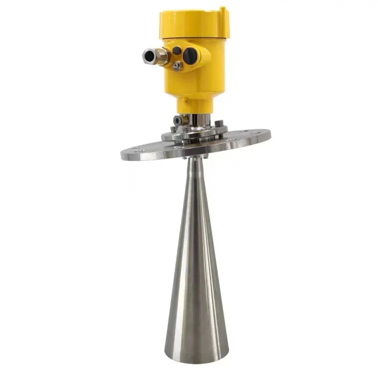
A top-mounted instrument normally measures the gap to the water, not water depth directly. If its reference is 3.0 m above the chosen tank zero and the measured gap is 1.2 m, the level is 1.8 m above that zero. As the tank fills, the gap decreases while level increases. Reversing those quantities in a controller can reverse the apparent process trend.
The chosen zero may be the tank floor, an outlet datum or another operating reference. Document it so the next technician can reproduce the conversion. Do not assume the underside of the lid is the instrument's measuring reference; the reference location depends on the sensor design.
Both radar and ultrasonic instruments need clearance at the highest water level as well as a usable target at the lowest level. A mounting point that works with a half-full tank can become unsuitable when the surface enters the near-field blind zone.
An ultrasonic sensor emits sound toward the surface and measures the returning echo. Distance is calculated as sound speed multiplied by round-trip travel time, divided by two. At an assumed sound speed of 343 m/s, a 10 ms round trip corresponds to approximately 1.715 m. This example illustrates the calculation, not a calibration condition for every tank.
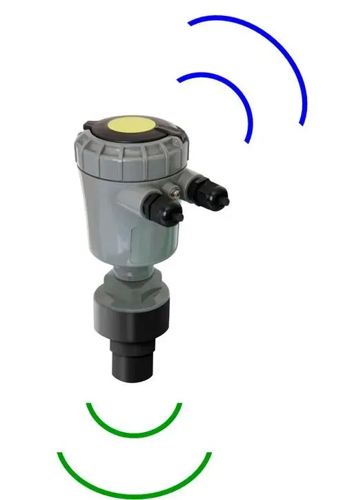
Sound speed changes with atmospheric conditions, so the instrument's compensation and the actual acoustic path matter. Foam, strong vapour conditions, temperature gradients and objects in the path can weaken or redirect the echo. A nearby inlet stream may become a target instead of the representative surface.
Ultrasonic measurement avoids placing the sensing element in water, but the sensor face still encounters the tank atmosphere. Check condensation and chemical compatibility rather than treating “non-contact” as complete isolation from the process.
A submerged pressure sensor uses P = ρ × g × h. Pressure P depends on liquid density ρ, gravity g and liquid head h above the sensing diaphragm. For an illustrative 2 m column of water at 1000 kg/m³ and g = 9.81 m/s², the gauge pressure is about 19.62 kPa.
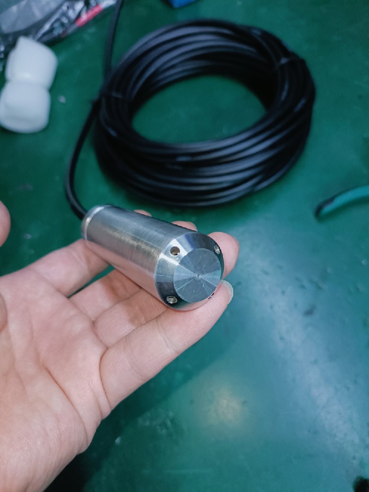
The measured head starts at the diaphragm, not automatically at the tank floor. If a probe is 0.15 m above the floor and measures 1.20 m of water above itself, the surface is 1.35 m above the floor. Keep that installation offset separate from a calibration correction.
A vented probe references atmospheric pressure through its cable. In an open tank, that allows the pressure contribution from the atmosphere to be excluded when the vent is dry and unobstructed. In a sealed tank with changing headspace pressure, an ordinary ambient-referenced probe cannot automatically distinguish gas pressure from water head.
Keep a submerged inlet clear of sediment and away from direct inlet jets or pump suction disturbance. There is no universal clearance that makes every tank suitable. A guide tube can stabilise the probe, but it must exchange water freely enough to track filling and emptying.
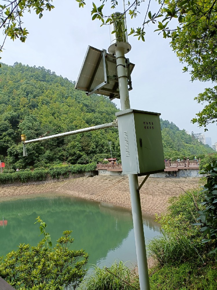
For overhead instruments, use a rigid mount and keep braces, pipes and walls out of the relevant beam path. For either method, movement of the mounting reference can appear as changing water level. A controller offset cannot compensate for a bracket that shifts between service visits.
Check access before choosing the position. The probe, sensor face and cable termination may need inspection even if the device has no moving mechanism. Avoid a location that requires unsafe entry or unnecessary process shutdown for routine service.
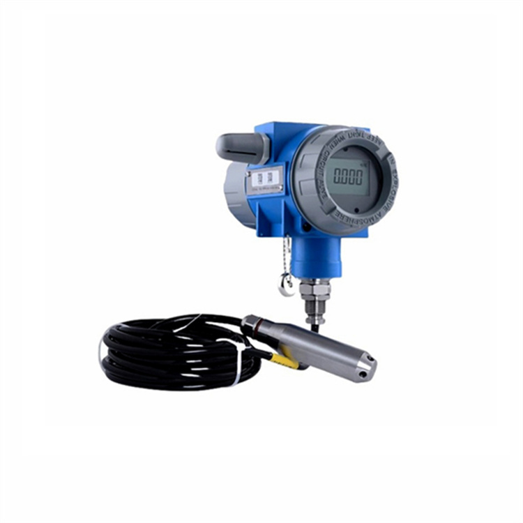
A continuous transmitter may supply 4–20 mA or a digital value such as RS485 Modbus RTU, depending on the selected model. These are interfaces, not measuring principles. Two instruments can use the same pressure principle while requiring different input hardware.
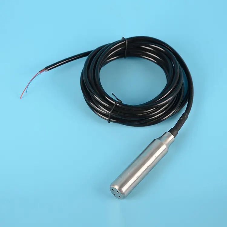
For a 4–20 mA output configured as 0–3 m, 12 mA represents 1.5 m because it is halfway through the 16 mA measuring span. This calculation assumes that configuration and does not apply to a differently scaled transmitter. Confirm whether the reported quantity is raw distance, head above the probe or already converted tank level before applying another offset.
The NiuBoL NBL-L-WLPS RS485 configuration connects to a compatible Modbus receiver. The NBL-L-SMP4603 current-output version instead requires a suitable analog input and loop supply. Neither an analog loop nor Modbus alone provides a direct internet connection; a logger or gateway handles any remote transmission.
For a vertical tank with a constant 2 m² horizontal area, a level of 1.5 m above the floor represents 3 m³ of gross geometric volume. A 0.1 m change represents 0.2 m³. A horizontal cylindrical tank does not have that constant area, so it needs its own geometry or volume table.
Gross volume is not necessarily usable water. An outlet above the floor, sediment, operating reserve and minimum pump submergence can reduce the available volume. Define those quantities before displaying “remaining capacity” in a dashboard.
Likewise, level change gives net storage change, not a direct inlet flow measurement. If a tank is filling and discharging at the same time, the level alone cannot separate those flows. Add the required flow measurements or use an appropriate controlled test if that distinction matters.
A radar level instrument sends an electromagnetic signal and derives distance from the return. FMCW radar varies the transmitted frequency and uses the relationship between transmitted and received signals to determine range. It does not use the speed of sound, so acoustic temperature compensation is not its measuring basis.
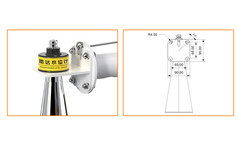
Radar still needs a suitable reflection and installation geometry. Foam, deposits on the antenna, nearby structures and surface movement can affect the result. Do not assume that any radar is suitable for a high-pressure vessel, hot process or hazardous area merely because it works without immersion.
| Quantity to check | Hydrostatic measurement | Overhead distance measurement |
|---|---|---|
| Directly sensed quantity | Pressure at the submerged diaphragm. | Distance to the reflecting surface. |
| Required reference | Probe position and pressure reference. | Sensor reference height and mounting position. |
| Typical disturbance | Density change, blocked vent, local flow pressure or deposits. | Obstacles, poor echoes, blind-zone entry or mounting movement. |
| Level conversion | Pressure-to-head conversion plus the installation offset. | Reference height minus measured gap. |
A float with a magnetic switch, a conductive electrode arrangement or an optical point detector can indicate whether liquid has reached a particular position. The exact output depends on the instrument. Do not assume that a point detector provides a continuous depth simply because it responds quickly.

Capacitive instruments respond to changes in the electrical properties around a probe or sensing area. Their suitability depends on liquid properties, vessel construction and buildup. Optical devices also vary in design; liquid transparency alone is not a universal selection rule.
For any of these methods, confirm the exact product configuration rather than selecting solely by the measuring principle. Response time, wetted materials and output must match the tank duty. Keep a separately assessed limit device where the process needs independent protection.
The water surface is moving closer to the overhead sensor. Convert distance to level using the documented reference height. Check whether the instrument or controller already performs that conversion before subtracting the value again.
They measure different physical quantities that can be converted to the same level reference. Pressure gives head above the diaphragm; an overhead sensor gives distance from its reference. Their installation offsets and uncertainties must be accounted for separately.
Only if it has been configured as volume using the correct geometry. A level percentage is normally a fraction of the measuring span. In an irregular or horizontal cylindrical tank, equal level increments do not represent equal volume increments.
It can support a storage-change calculation when geometry and operating conditions are known. Simultaneous inflow, outflow and other losses prevent level alone from identifying consumption. Use an appropriate flow measurement when that quantity is required.
No. RS485 is a local electrical interface, and Modbus RTU defines the device exchange. A compatible receiver and the required gateway, network and server arrangement are needed for remote viewing.
Check units, datum, distance-versus-level selection and any duplicated offset first. Then compare the raw signal with an independent reference and inspect the vent or echo path. Do not recalibrate a sensor simply to hide an installation-reference error.
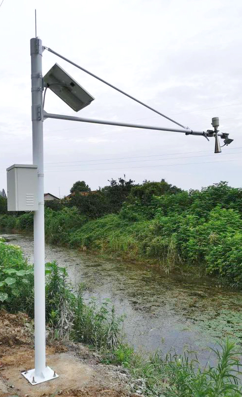
A tank level reading is the result of a sensing principle, a known reference and a correctly interpreted signal. Choose the method for the tank conditions, then verify the conversion before using the result for volume or control. For a NiuBoL configuration review, provide tank geometry, maximum and minimum levels, mounting access and the receiving input type.
Prev:Continuous Level Sensor vs Float Switch: When More Data Helps
Next:How to Measure Liquid Level: References, Methods and Field Checks
Related recommendations
Sensors & Weather Stations Catalog
 Agriculture Sensors and Weather Stations Catalog-NiuBoL.pdf
Weather Stations Catalog-NiuBoL.pdf
Agriculture Sensors Catalog-NiuBoL.pdf
Water Quality Sensor Catalog-NiuBoL.pdf
Related products
 Combined air temperature and relative humidity sensor
 TDR Soil Moisture & Temperature Sensor for irrigation| RS485 |4-20mA| NBL-S-THR
 Soil pH sensor RS485 soil Testing instrument soil ph meter for agriculture |NBL-S-PH
 Wind Speed sensor Output Modbus/RS485/Analog/0-5V/4-20mA
 Tipping bucket rain gauge for weather monitoring auto rainfall sensor RS485/Outdoor/stainless steel
 Pyranometer Solar Radiation Sensor 4-20mA/RS485


Screenshot, WhatsApp to identify the QR code
WhatsApp number:+8615367865107
(Click on WhatsApp to copy and add friends)

