





— Blogs —
—Products—
 Consumer hotline +8618073152920
WhatsApp:+8615367865107
Address:Room 102, District D, Houhu Industrial Park, Yuelu District, Changsha City, Hunan Province, China
Product knowledge
Time:2024-10-24 14:42:38 Popularity:3690
A rain sensor in IoT supplies a rainfall-related observation to a receiving system. The useful integration question is what each data field means: rain presence, bucket count, accumulated depth or intensity. Define the quantity, unit and time period before mapping the field into a PLC, RTU, data logger or server. A successful connection does not establish that a rainfall value has been interpreted correctly.
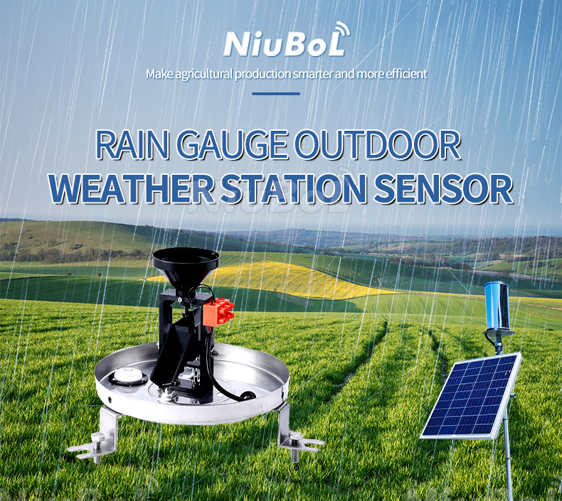
A field containing 4 could mean four bucket tips, 4 mm since a reset, 4 mm during an interval or an intensity of 4 mm/h. These are different observations. Put the definition beside the interface mapping rather than leaving the receiving developer to infer it from the number or a dashboard label.
Start at the selected instrument output. A contact closure needs a suitable counting input. An RS485 device needs the actual protocol and register definitions. A server message may then represent a processed quantity rather than the raw sensor output. Identify where that conversion occurs so the same count is not converted twice.
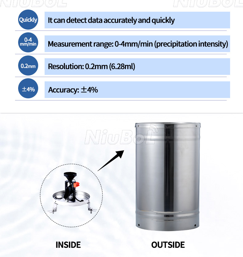
Tipping buckets measure discrete collected-water increments. Piezoelectric instruments process droplet impacts into their defined rainfall quantities. A network connection does not make these methods equivalent or make either instrument measure root-zone moisture. Choose the rainfall duty first, then configure its data path.
The NBL-W-PRS has RS485 Modbus output and a 0-8 mm/min intensity range, with 0.01 mm resolution and a stated +/-4% daily cumulative-rainfall accuracy. The daily-total accuracy basis does not establish the accuracy of every short intensity interval. Keep the delivered field definitions specific to this model and version.

| Data item | Definition to establish | Error prevented |
|---|---|---|
| Observation identity | Station, gauge and physical location | Assigning another site's rain to the current field |
| Quantity and unit | Count, presence, mm, mm/min or mm/h | Displaying counts as depth or a rate as an amount |
| Period | Interval start/end or accumulation/reset basis | Adding overlapping totals or using the wrong duration |
| Observation time | Measurement time and time zone, distinct from receipt time | Moving late records into the wrong rainfall period |
| Validity | Valid dry observation, missing record, test or fault | Turning unknown rain into zero rain |
| Conversion configuration | Tip increment or applicable instrument scaling | Applying a different model's conversion factor |
Some of these fields belong in the logger configuration or server record rather than the sensor response. Use the selected device's register map for exact addresses, scaling and data types. Then document how those values become the rainfall fields accepted by the receiving application.
For an illustrative 0.2 mm-per-tip configuration, 20 valid tips represent 20 x 0.2 = 4 mm. A 0.5 mm-per-tip configuration would give 10 mm for the same count. Check the actual gauge version before setting the multiplier, especially when the housing and product family name look similar.
The standard NBL-W-RS configuration lists 0.2 mm resolution, a 0-4 mm/min intensity range and selected contact, voltage or RS485 outputs. The technical documents below also cover other configurations. Order and configure the actual rainfall increment, not one copied from an unrelated drawing.
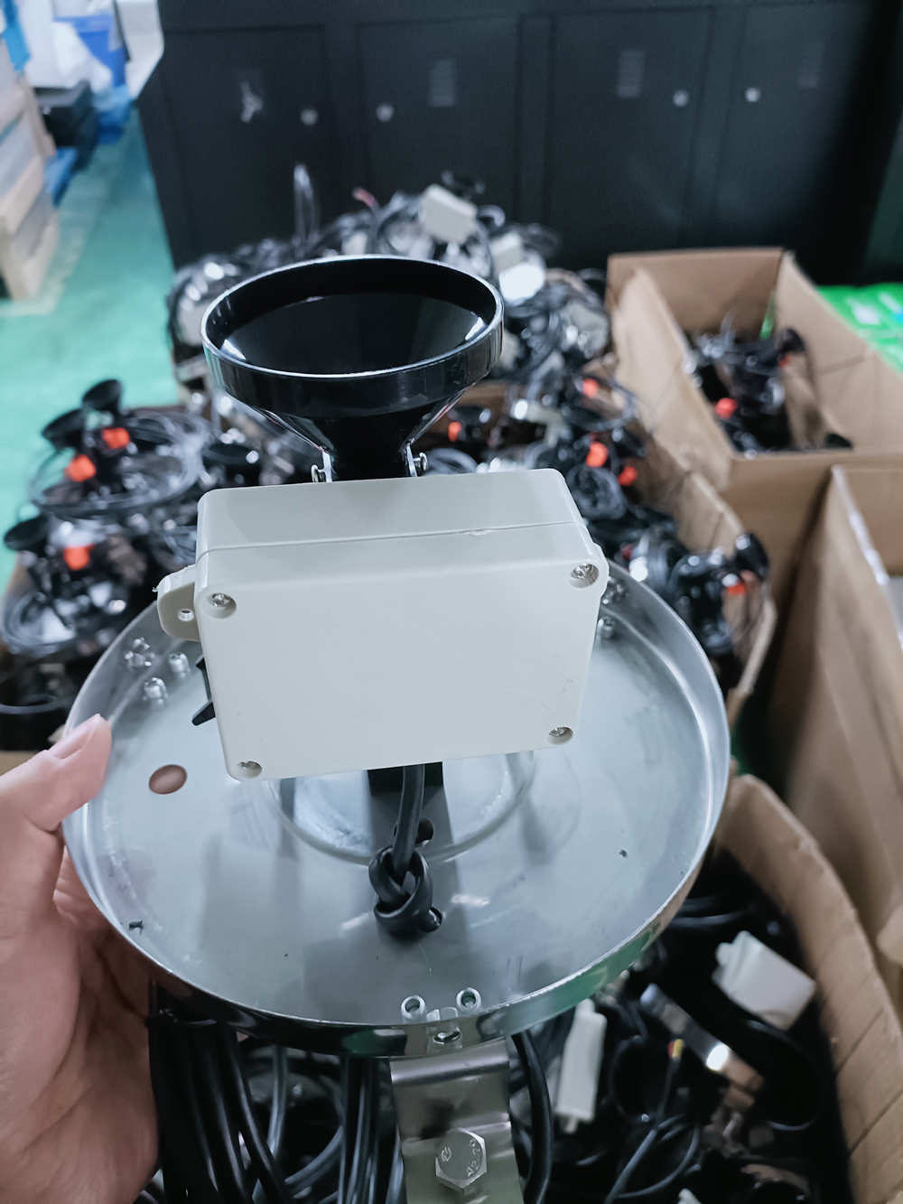
A reed contact has an opening and a closing transition. Configure the receiver for the intended event rather than counting both transitions as two tips. Check contact bounce and the input requirements for the selected acquisition hardware; there is no universal debounce time that should be assigned without those details.
Use an approved functional test to compare a known number of mechanical tips with the receiver count and the converted depth. A counting test demonstrates the acquisition conversion, not the gauge's volumetric calibration. Keep artificial test counts out of the operational rainfall record using the project's defined procedure.
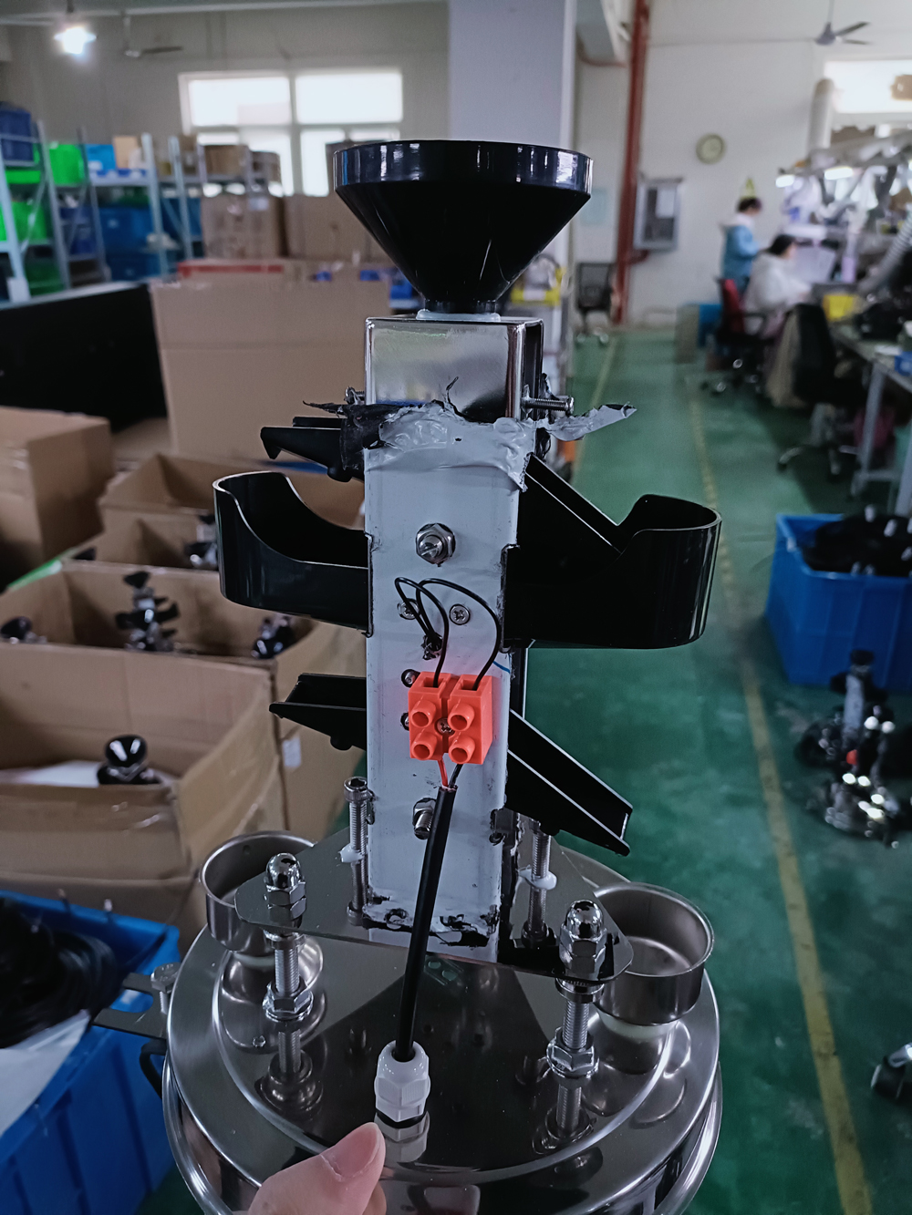
If the illustrative 4 mm accumulation covers exactly ten minutes, its interval-average intensity is 4 / (10 / 60) = 24 mm/h, equivalent to 0.4 mm/min. That is not the peak intensity within those ten minutes. A longer averaging period can hide short bursts even when the interval total is correct.
When a sensor supplies its own intensity value, retain its defined time basis. Do not divide it by the upload interval as though it were an accumulated depth. Conversely, an uploaded interval total needs the actual represented duration before a rate is calculated. Upload frequency and measurement period need not be the same.
A cumulative counter is a state since a defined origin. An interval total is an amount assigned to a stated period. Repeated transmission of the same cumulative total must not add that total again, while distinct interval amounts can only be summed when their periods are compatible and non-overlapping.
Counter reset and communications recovery need their own checks. The rainfall-record continuity guide covers outage and reset handling. Keep this behaviour separate from the physical measuring range; a software counter limit is not a maximum amount of rain the collector can observe.
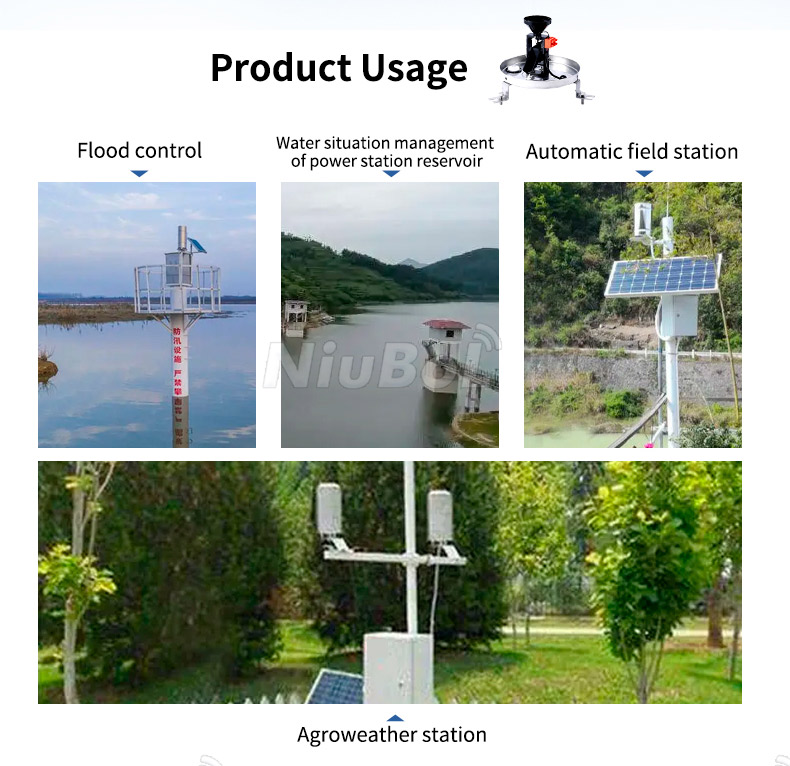
A TG462 / TG462S data logger can form part of the sensing-to-server chain. Identify the receiving input, channel conversion and destination format for the ordered configuration. Do not assume that RS485 always means Modbus RTU or that a configured cellular connection automatically implements a customer's message format.
Before accepting the integration, trace one identified observation from the instrument through the logger into the export or receiving platform. Compare quantity, unit, period, location and validity. In an irrigation or drainage project, those fields make the rainfall record usable; they do not create soil-water, water-level or automatic control measurements that were never supplied.
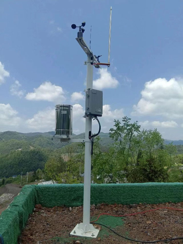
Its definition must identify the quantity, unit and period or reset basis. A name alone cannot distinguish an interval depth from a cumulative counter or an intensity.
No. Confirm the actual rainfall increment and output configuration. Using 0.2 mm instead of 0.5 mm changes the inferred depth even when the tip count is correct.
No. It describes the amount divided by that ten-minute duration. The rainfall may have varied within the period.
It verifies part of the counting and conversion chain. Quantitative gauge performance requires the appropriate volumetric or reference evaluation and suitable exposure.
Only if that matches the defined acquisition arrangement. Delayed delivery can otherwise assign a valid observation to the wrong interval. Retain measurement timing separately when records can arrive late.
Provide the gauge model and output version, required rainfall quantities and periods, receiving input or protocol, destination format and site conditions. Include whether the scope is a bare instrument or a complete powered reporting station.
Select the document for the installed gauge and output configuration when checking connections, increments and data definitions.
 NBL-W-RS-Tipping-bucket-rain-gauge-instruction-manual-0.5mm.pdfNBL-W-ARS-Tipping-bucket-rain-gauge-instruction-manual.pdfNBL-W-RS-Rain-sensors-instruction-manual-V4.0.pdfNBL-W-DRS-Double-Tipping-Bucket-Rain-Sensor-Instruction-Manual.pdfNBL-W-PRS-Piezoelectric-Rain-Sensor-Operator's-Manual.pdf
Integrate a rain sensor in IoT by mapping a defined observation, not an ambiguous rain number. Preserve the quantity, unit, location and time basis through conversion and transmission. Verified field meanings make the record useful before any platform adds a chart, alarm or control response.
Prev:Simple Weather Station: Define the Minimum Useful Configuration
Next:Portable Weather Station: Handheld Survey or Tripod Installation?
Related recommendations
Sensors & Weather Stations Catalog
 Agriculture Sensors and Weather Stations Catalog-NiuBoL.pdf
Weather Stations Catalog-NiuBoL.pdf
Agriculture Sensors Catalog-NiuBoL.pdf
Water Quality Sensor Catalog-NiuBoL.pdf
Related products
 Combined air temperature and relative humidity sensor
 TDR Soil Moisture & Temperature Sensor for irrigation| RS485 |4-20mA| NBL-S-THR
 Soil pH sensor RS485 soil Testing instrument soil ph meter for agriculture |NBL-S-PH
 Wind Speed sensor Output Modbus/RS485/Analog/0-5V/4-20mA
 Tipping bucket rain gauge for weather monitoring auto rainfall sensor RS485/Outdoor/stainless steel
 Pyranometer Solar Radiation Sensor 4-20mA/RS485


Screenshot, WhatsApp to identify the QR code
WhatsApp number:+8615367865107
(Click on WhatsApp to copy and add friends)

