

— Blogs —
—Products—
 Consumer hotline +8618073152920
 WhatsApp:+8615367865107
Address:Room 102, District D, Houhu Industrial Park, Yuelu District, Changsha City, Hunan Province, China
Product knowledge
Time:2026-07-20 13:29:14 Popularity:287
A water quality monitoring sensor is only useful when the host system can read, scale, store and act on the data correctly. PLC, SCADA and IoT gateway integration should be planned before shipment. Most field problems come from address conflicts, wrong wiring, incorrect scaling, missing temperature channels or unclear alarm logic.
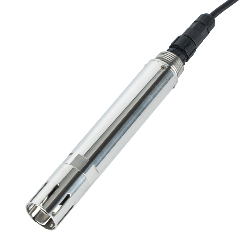
The path includes sensor, cable, junction box, power supply, data logger or PLC, communication network and platform. Each part needs a clear owner. A supplier can provide the sensor, but the integrator must know where data units are converted and where alarms are created.
| Interface | Where it fits | Main check |
|---|---|---|
| RS485 Modbus RTU | Multiple digital sensors on a bus | Address, baud rate, register map and grounding. |
| 4-20 mA | Legacy PLC analog input | Scaling, loop power and analog isolation. |
| RTU or data logger | Remote stations and cloud upload | Power budget, polling interval and storage. |
| SCADA | Plant operation and alarm management | Tag names, engineering units and alarm setpoints. |
| IoT gateway | Remote dashboard and multi-site management | Network coverage and data ownership. |
NiuBoL pH, DO, residual chlorine, conductivity, ammonia nitrogen, turbidity and TSS sensors support RS485 Modbus RTU in the verified manuals. Selected 4-series models also provide optional 4-20 mA output. The Modbus communication default shown in the pH manual is 9600 bps, no parity, 8 data bits and 1 stop bit, with customizable parameters by project.
| Parameter | Verified specification or buyer note |
|---|---|
| Model | NBL-WQ-PH / NBL-WQ-PH-4A / NBL-WQ-PH-4S |
| Measuring range | 0 to 14 pH |
| Resolution | 0.01 pH |
| Accuracy | ±0.1 pH, temperature ±0.3°C |
| Temperature compensation | Automatic, NTC |
| Power supply | 12 to 24 VDC |
| Signal output | RS485 Modbus RTU; 4-20 mA optional on 4-series models |
| Protection | IP68, immersion mounting, 3/4 NPT |

When several water quality sensors share one RS485 line, the integrator should assign unique addresses, check total cable length, avoid star wiring where possible, manage termination, separate power noise and record register maps. A bus that works on a desk can fail in the field if grounding, cable shield and surge protection are ignored.
Analog output is simple, but scaling must be documented. For example, 4 mA and 20 mA should correspond to a known pH, DO, chlorine or conductivity range. If the PLC scaling is wrong, the dashboard may show plausible but incorrect data. Acceptance should include low-point and high-point simulation or reference check.
| Test | What to verify |
|---|---|
| Power and polarity | 12 to 24 VDC supply, correct wiring and waterproof termination. |
| Communication | Address, baud rate, register, unit and decimal position. |
| Reading comparison | Reference buffer, portable meter or controlled sample. |
| Alarm logic | Warning, emergency and maintenance states. |
| Data storage | Historical record, time stamp and export. |
| Maintenance flag | Cleaning and calibration periods do not become false process alarms. |
For an RFQ, send water type, expected concentration range, temperature, pressure, installation method, cable length, output preference, quantity and destination country. For PLC, SCADA or IoT water quality integration, include whether the point is for spot checking, closed-loop control, alarm evidence or long-term trend records.
For contractor projects, also define who supplies the cabinet, controller, sampling line, power supply, lightning protection, civil work and communication card. Clear supply boundaries prevent delays during commissioning and make quotations easier to compare.
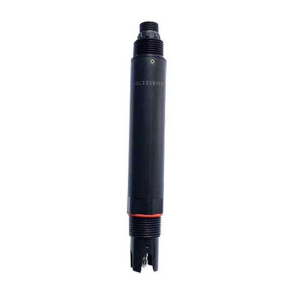
The most useful documents are wiring definition, power requirement, Modbus register map, default communication settings, calibration commands if available, output scaling and installation guide. These documents should be sent to the PLC or SCADA engineer before the hardware arrives. Waiting until site commissioning wastes time and can create wrong assumptions.
For RS485 Modbus RTU, the integrator should know slave address, baud rate, parity, stop bits, function code, register address, data type, decimal position and engineering unit. For 4-20 mA, the integrator should know the exact range represented by 4 mA and 20 mA.
| Document | Who uses it | Why it matters |
|---|---|---|
| Wiring diagram | Electrician and panel builder | Prevents polarity and output mistakes. |
| Register map | PLC/SCADA engineer | Maps values to correct tags and units. |
| Calibration guide | Commissioning team | Supports verification and maintenance. |
| Installation guide | Site contractor | Prevents wrong mounting and water damage. |
| Packing list | Procurement and warehouse | Confirms accessories before field work. |
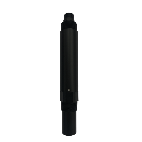
For multi-sensor projects, build a bench test before field installation. Power one sensor, confirm communication, read values, change address if needed and document the tag name. Then add sensors one by one. This reduces the chance that several address or wiring problems appear at the same time on site.
A simple factory acceptance test can include pH buffer response, DO air reading trend, conductivity solution check or chlorine reference test depending on available materials. The goal is not to replace final calibration, but to confirm that the data path works.
IoT gateway projects should clarify who owns platform access, who can export data, how long records are stored and what happens when a SIM card or cloud account expires. These issues are commercial as much as technical. They should be discussed before purchase, especially for distributors and contractors handing systems to end users.
For plants with strict network rules, local PLC or SCADA integration may be preferred over cloud access. NiuBoL can support either discussion if the buyer provides host system details and communication requirements.
A common failure is reversed RS485 A/B wiring. Another is using the wrong register address or forgetting the decimal position. Analog systems fail when 4-20 mA scaling in the PLC does not match the sensor range. Remote systems fail when the gateway has weak signal, insufficient power or no clear data ownership.
These problems are avoidable with a bench test and a commissioning sheet. The sheet should list sensor serial number, Modbus address, baud rate, register, unit, cable route, power supply and platform tag name. For multiple sensors, the integrator should keep one row per sensor.
| Failure | Symptom | Prevention |
|---|---|---|
| Duplicate Modbus address | Only one sensor responds or values conflict | Assign and record addresses before installation. |
| Wrong decimal scaling | Value looks ten or hundred times wrong | Check register map and example values. |
| No surge protection | Failure after storms | Use suitable grounding and protection. |
| Unclear cloud account | Owner cannot access data later | Define account ownership in project scope. |
A useful RFQ states the host PLC or gateway model, number of sensors, cable distance, power supply, required parameters, preferred output, whether cloud upload is needed and who performs field wiring. It also asks for wiring diagrams and Modbus register maps before shipment.
After integration, the owner should receive a file package that includes as-built wiring, sensor address list, PLC tag list, platform account information, calibration records and spare-part recommendations. Without these files, the next maintenance engineer may have to reverse-engineer the system from the cabinet wiring.
For OEM and distributor projects, standardized handover files are valuable. They make repeated projects faster and reduce support cost. NiuBoL can provide sensor-side documents, while the integrator should add site-specific wiring, tag names and platform settings.
| Handover file | Owner benefit |
|---|---|
| Address list | Prevents Modbus conflicts during replacement. |
| Tag list | Keeps SCADA units and labels consistent. |
| Calibration record | Shows baseline measurement quality. |
| Spare list | Reduces downtime after sensor damage. |
Before the site team starts wiring, hold a short technical review with the sensor supplier, panel builder and automation engineer. Confirm power supply, RS485 cable route, shield grounding, device addresses, register maps, tag names and alarm responsibility. This meeting can prevent several days of field debugging.
For remote IoT systems, also confirm network coverage, SIM card ownership, data plan, platform login and who receives alarms. These are not only IT details. If the gateway cannot upload data or no one owns the account, the monitoring system will not deliver project value.
A practical commissioning method is to connect one sensor first, confirm values, then add the second sensor after assigning a different Modbus address. Continue one sensor at a time until the full bus is built. This makes troubleshooting much easier than connecting all sensors first and then trying to identify which address or wire is wrong.
After the bus is stable, the engineer should export or screenshot the PLC tag list and platform page. These records make future replacement easier because the next technician can match physical sensor, address and displayed parameter.
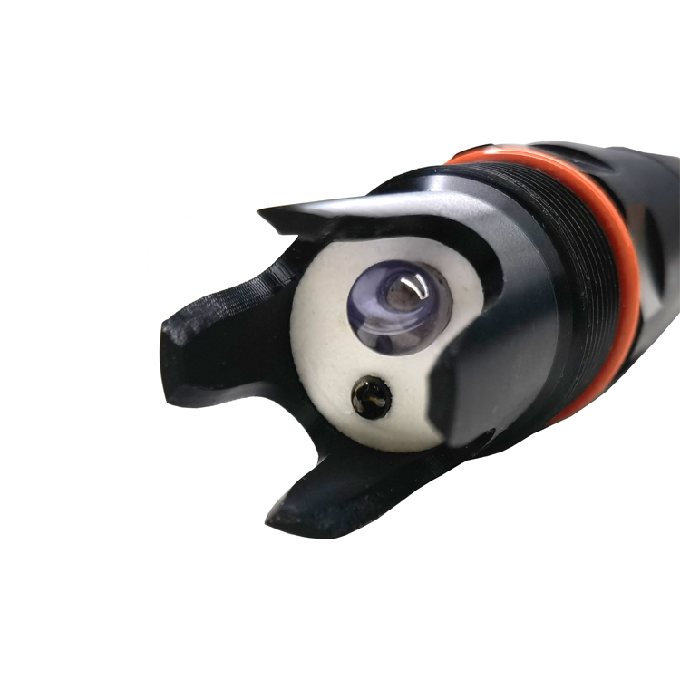
A: RS485 Modbus RTU is common across the verified water quality sensor manuals.
A: Use 4-20 mA when the PLC has analog input and the project needs a simple single-value signal with documented scaling.
A: Wrong A/B wiring, duplicate address, baud-rate mismatch, register error, grounding noise and missing decimal scaling are common causes.
A: Yes, if addresses, cable layout, termination, power and polling interval are designed correctly.
A: Request wiring diagram, Modbus register map, power requirement, output scaling, installation guide and calibration method.
A: Use explicit units and decimal positions in PLC tags and platform displays. Do not rely on sensor name alone.
A: Test sensor reading, temperature channel if available, communication, alarms, historical storage and maintenance flags.
A: Not always. A gateway uploads data, but local control, power distribution and alarm logic may still need a controller or PLC.
A: Provide host model, input type, communication protocol, point count, cable distance, power source and required parameters.
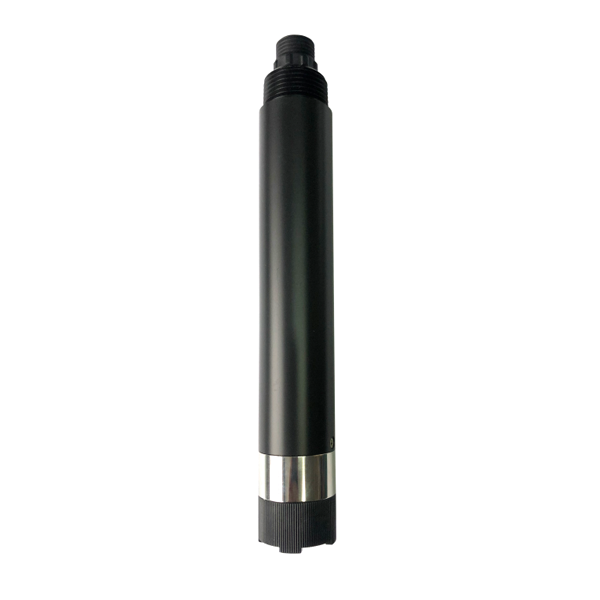
Water quality sensor integration should be specified from the sensor tip to the platform tag. RS485 Modbus RTU, optional 4-20 mA, power design, register scaling, grounding and acceptance testing must be planned together. NiuBoL can support PLC, SCADA and IoT gateway projects when the host system details are provided before ordering.
 NBL-WQ-CL Water Quality Sensor Online Residual Chlorine Sensor.pdf
NBL-WQ-DO Online Fluorescence Dissolved Oxygen Sensor.pdf
NBL-WQ-NHN Ammonia Nitrogen Water Quality Sensor.pdf
NBL-WQ-COD Online Water Quality COD Sensor.pdf
NBL-WQ-PH Online pH Water Quality Sensor.pdf
NBL-WQ-EC water quality conductivity sensor.pdf
Prev:Real Time Water Quality Monitoring System: Parameters, Sampling Rate and Alerts
Next:Online pH Meter Buying Guide for Continuous Water Monitoring
Related recommendations
Sensors & Weather Stations Catalog
Agriculture Sensors and Weather Stations Catalog-NiuBoL.pdf
Weather Stations Catalog-NiuBoL.pdf
Agriculture Sensors Catalog-NiuBoL.pdf
Water Quality Sensor Catalog-NiuBoL.pdf
Related products
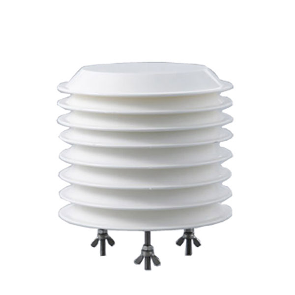 Combined air temperature and relative humidity sensor
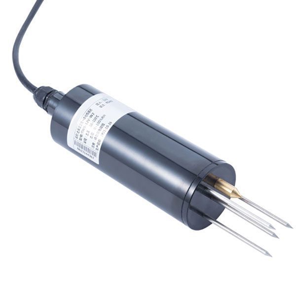 TDR Soil Moisture & Temperature Sensor for irrigation| RS485 |4-20mA| NBL-S-THR
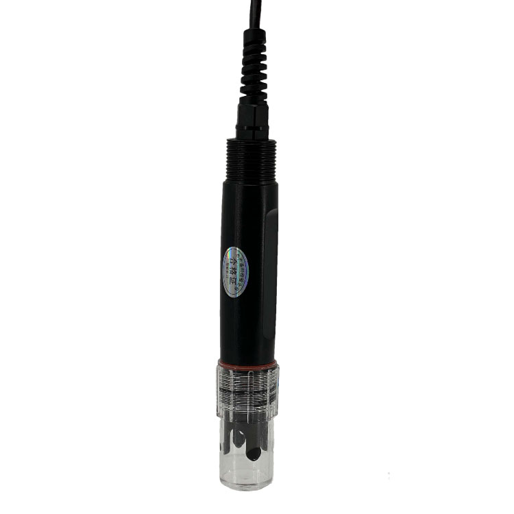 Soil pH sensor RS485 soil Testing instrument soil ph meter for agriculture |NBL-S-PH
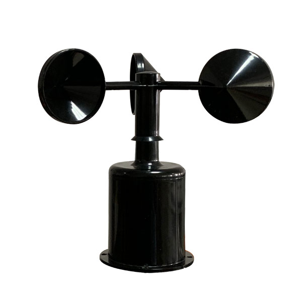 Wind Speed sensor Output Modbus/RS485/Analog/0-5V/4-20mA
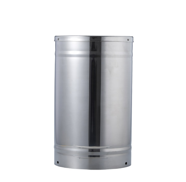 Tipping bucket rain gauge for weather monitoring auto rainfall sensor RS485/Outdoor/stainless steel
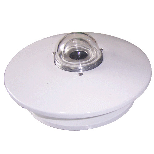 Pyranometer Solar Radiation Sensor 4-20mA/RS485

Screenshot, WhatsApp to identify the QR code
WhatsApp number:+8615367865107
(Click on WhatsApp to copy and add friends)