
— Blogs —
—Products—
 Consumer hotline +8618073152920
 WhatsApp:+8615367865107
Address:Room 102, District D, Houhu Industrial Park, Yuelu District, Changsha City, Hunan Province, China
Product knowledge
Time:2026-08-11 09:06:00 Popularity:156
A liquid conductivity sensor is used when a project needs continuous EC, conductivity or salinity-related trend data in water treatment, aquaculture, industrial water loops or environmental stations. The buying decision should focus on water matrix, installation method, temperature compensation, communication interface and maintenance access, not only on the phrase printed in the quotation.
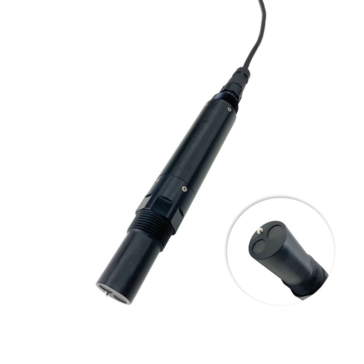
For integrators, the sensor must fit the actual hydraulic layout. Conductivity data is useful only when the probe is installed in a representative sample point, connected correctly to the cabinet, and checked against the operating process after commissioning.
Conductivity can indicate dissolved ionic content, process water change, RO pretreatment condition, saline intrusion, dosing variation or abnormal discharge. The project should define which decision the value supports: alarm, trend report, control interlock, manual inspection or water-quality comparison.
If the project needs TDS or salinity display, confirm whether the platform calculates those values from conductivity and which conversion basis is used. This should be documented before data is compared between different instruments.
| Selection item | Project check | Why it matters |
|---|---|---|
| Water matrix | Clean water, wastewater, aquaculture water, RO loop or industrial process water | Determines fouling risk and maintenance interval |
| Measurement output | Conductivity, EC, TDS or salinity-related value by configuration | Prevents confusion between direct measurement and calculated display |
| Power supply | DC 12-24 V in common monitoring cabinets | Matches field terminal, solar station or control cabinet |
| Communication | RS485 Modbus RTU or compatible signal output | Supports PLC, RTU, data logger and IoT gateway integration |
| Installation | Immersion, flow-through or pipe-mounted arrangement | Affects sample representativeness and cleaning access |
| Temperature compensation | Compensation rule confirmed in the data system | Improves comparison across changing water temperatures |
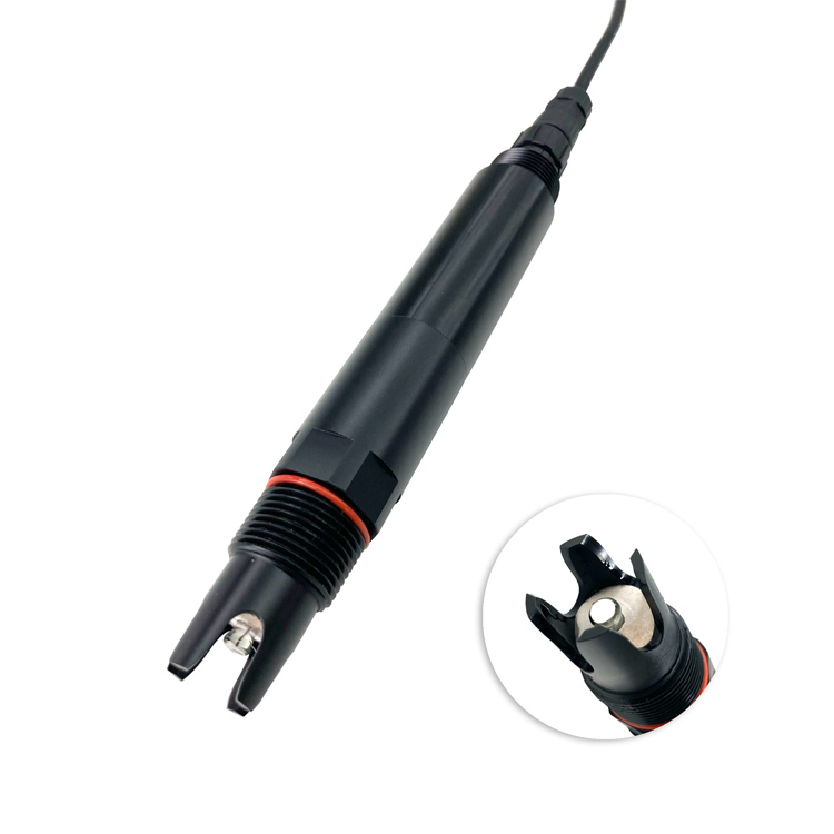
The probe should be placed where the sample represents the process. Avoid dead zones, chemical injection points, air bubbles, sediment accumulation and positions where the water level may expose the sensing area. In pipe or flow-through installations, confirm flow stability and service access before ordering accessories.
For open tanks and channels, the bracket should protect the cable and allow the probe to be lifted for cleaning. A difficult maintenance position increases long-term cost even when the sensor price is attractive.
For RS485 Modbus RTU integration, confirm device address, baud rate, parity, register map, engineering unit, decimal place and update interval. If the project uses several probes in one cabinet, reserve addresses and power capacity in the drawing. Shielding, grounding and cable separation are important around pumps, mixers and dosing equipment.
The platform should label conductivity, TDS or salinity values clearly so operators know which value is measured and which value is calculated. This is especially important when reports are reviewed by different departments.
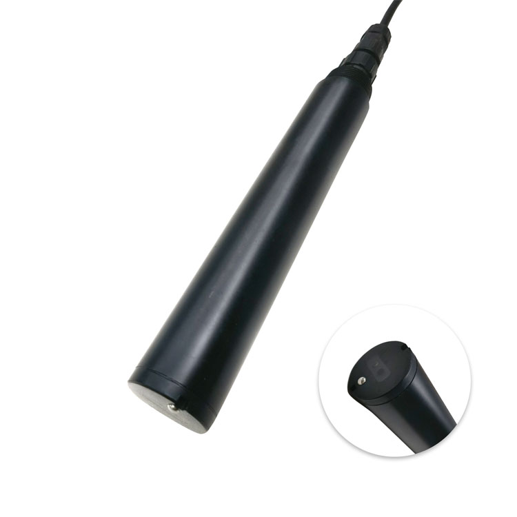
RO pretreatment and industrial water loops: conductivity trend helps identify water-quality change before it affects downstream equipment. Alarm thresholds should match process requirements and not only the sensor range.
Aquaculture and irrigation water: salinity-related changes may affect biological or crop conditions. The installation should allow periodic checking and cleaning without stopping the whole system.
Environmental monitoring stations: conductivity can help identify runoff, mixing, saline intrusion or unusual discharge events. The station design should include power, communication and maintenance records.
Conductivity sensors require a maintenance plan matched to the water matrix. Fouling, oil film, scaling, biofilm and trapped bubbles can change readings. The project file should define cleaning interval, verification solution or comparison method, and the person responsible for reviewing abnormal trends.
Acceptance should include live reading, communication response, unit display, temperature compensation setting, platform trend and a field photo of the installation. Keep these records with the cabinet documentation.
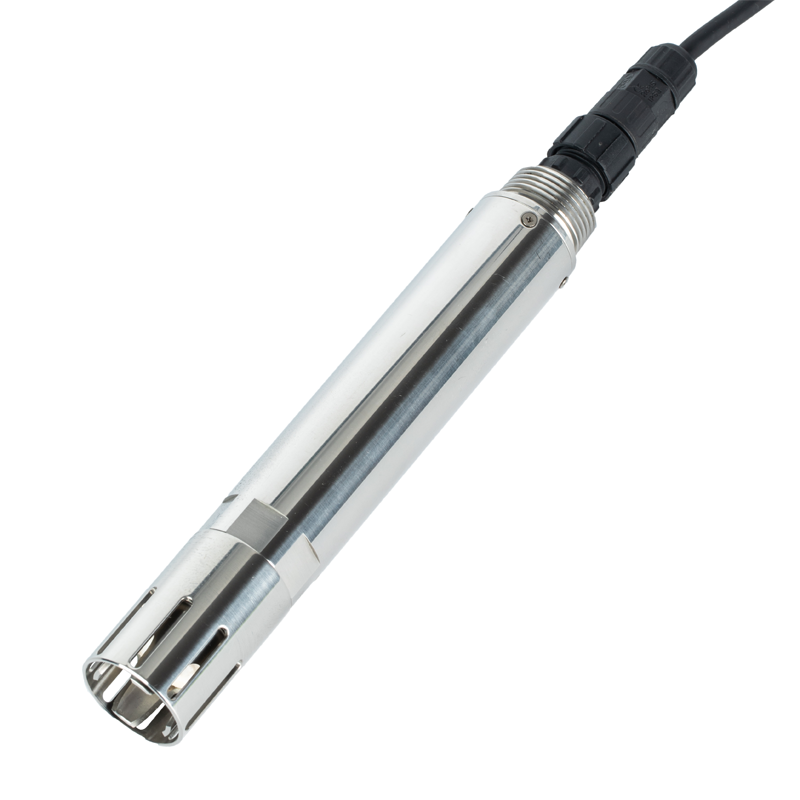
Confirm the measurement purpose, installation environment, signal output, power supply, cable route, data platform, maintenance access, and acceptance record. These details help the project team avoid field changes after procurement.
Match the communication interface, address plan, polling interval, unit display, alarm rule, and cabinet wiring with the existing gateway or controller. The integration document should be approved before site work starts.
Temperature, moisture, fouling, vibration, flow condition, cable distance, enclosure position, and service access can all affect long-term stability. The final selection should follow the real installation point, not only the catalog text.
The RFQ should include target parameter, range, output protocol, supply voltage, cable length, mounting method, enclosure requirement, quantity, project location, and any platform or data format requirement.
Acceptance should verify live value, unit, timestamp, wiring, address, platform channel, alarm action, photos, and the first stable data records. Keeping this evidence makes later operation easier to support.
Define cleaning, inspection, calibration or comparison method, spare parts, responsible team, and service interval according to the medium and site access. A clear plan reduces unexpected downtime.
Yes, but each site should use a consistent naming rule, address list, installation photo standard, and data template. This keeps commissioning and future expansion easier to manage.
NiuBoL can review the application condition, help match the sensor package, provide interface information, and support model selection for project teams that need reliable field data.
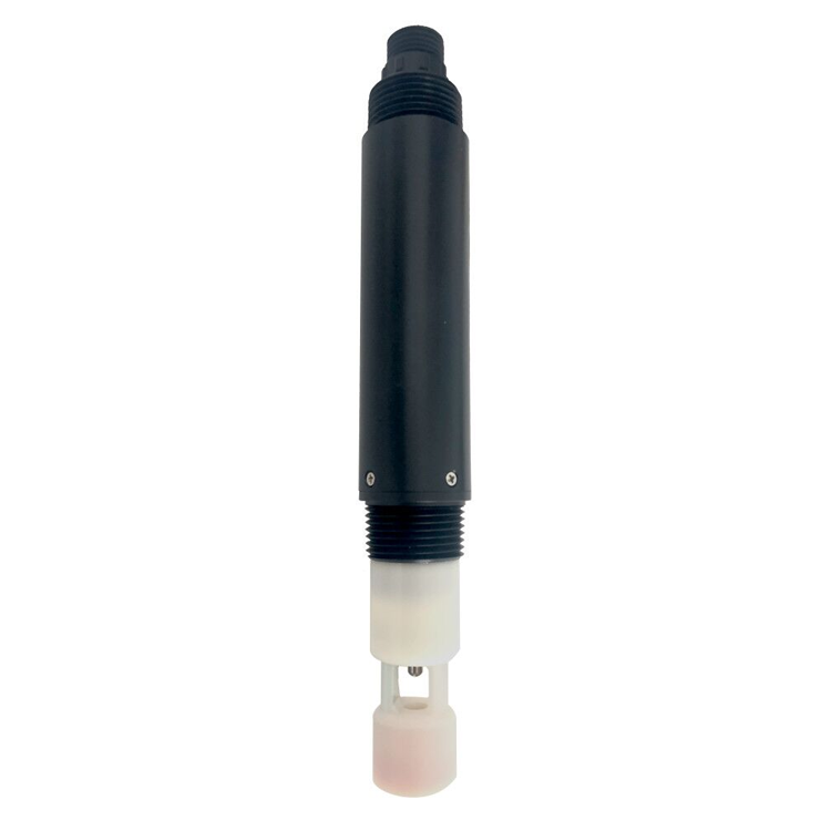
A liquid conductivity sensor should be specified as part of the complete water monitoring loop. Clear decisions about water matrix, installation, RS485 Modbus RTU communication, temperature compensation, cleaning access and acceptance evidence help the project obtain stable and useful EC data.
Prev:Total Suspended Solids Meter: Industrial Selection Guide for Online Monitoring Projects
Next:Liquid pH Sensor: Industrial Selection Guide for Online Monitoring Projects
Related recommendations
Sensors & Weather Stations Catalog
 Agriculture Sensors and Weather Stations Catalog-NiuBoL.pdf
Weather Stations Catalog-NiuBoL.pdf
Agriculture Sensors Catalog-NiuBoL.pdf
Water Quality Sensor Catalog-NiuBoL.pdf
Related products
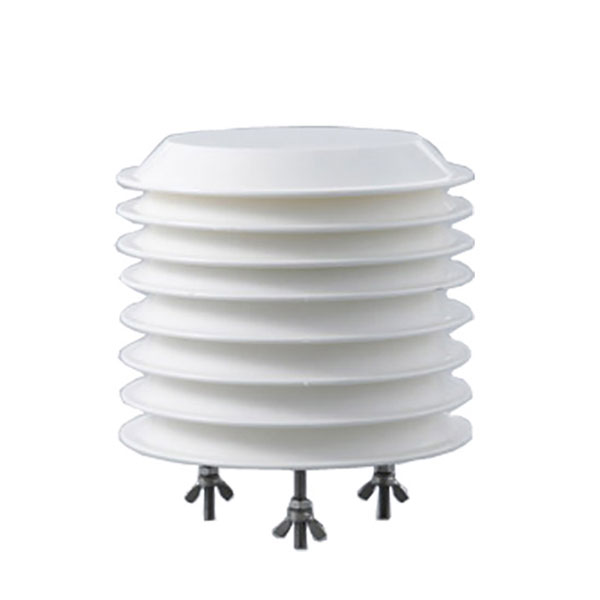 Combined air temperature and relative humidity sensor
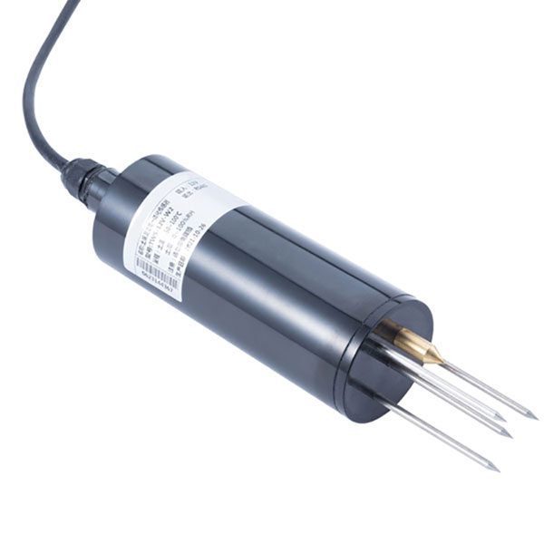 TDR Soil Moisture & Temperature Sensor for irrigation| RS485 |4-20mA| NBL-S-THR
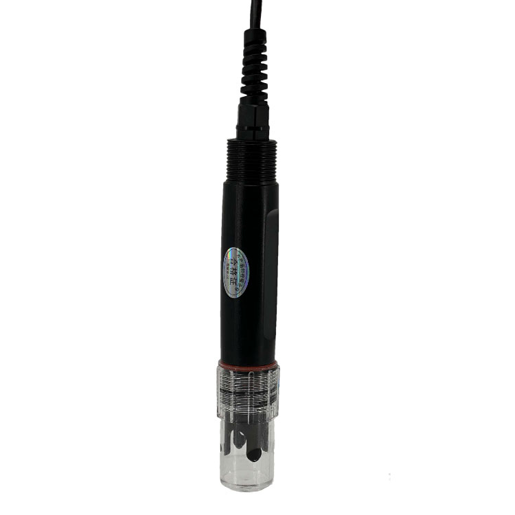 Soil pH sensor RS485 soil Testing instrument soil ph meter for agriculture |NBL-S-PH
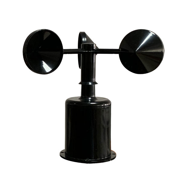 Wind Speed sensor Output Modbus/RS485/Analog/0-5V/4-20mA
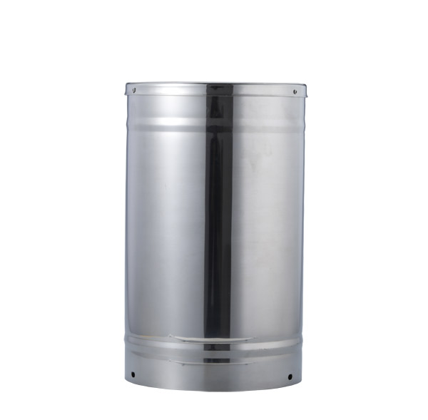 Tipping bucket rain gauge for weather monitoring auto rainfall sensor RS485/Outdoor/stainless steel
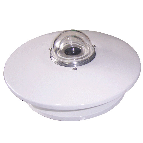 Pyranometer Solar Radiation Sensor 4-20mA/RS485
Screenshot, WhatsApp to identify the QR code
WhatsApp number:+8615367865107
(Click on WhatsApp to copy and add friends)