





— Blogs —
—Products—
 Consumer hotline +8618073152920
WhatsApp:+8615367865107
Address:Room 102, District D, Houhu Industrial Park, Yuelu District, Changsha City, Hunan Province, China
Product knowledge
Time:2026-08-12 09:05:00 Popularity:249
Quick Answer: A smart irrigation control set needs a suitable soil measurement, a controller that interprets it, and a hydraulic system that can deliver and stop water safely. Select the sensing method and location for each irrigation zone before setting thresholds. RS485 connectivity and a working relay do not prove that the root zone received the intended water.

A soil probe measures a local condition; it does not decide how much water a crop needs by itself. A controller combines that observation with the operating rules, while valves, pumps and pipework perform the irrigation. Flow and pressure feedback, where needed, show whether the commanded action actually occurred.
For a retrofit, identify what already exists. An irrigation cabinet may have usable inputs and valve control but lack a soil measurement. Another site may need monitoring only, with irrigation still scheduled by an operator. Supplying a complete new control package is unnecessary when a compatible sensor and acquisition change solve the actual gap.
| Part of the loop | Required decision | Failure to avoid |
|---|---|---|
| Soil observation | Water content, water potential, temperature or another defined variable | Using a channel that does not describe the intended root-zone condition. |
| Controller | Start and stop rules, permitted windows, maximum run and invalid-input response | Repeated or unlimited watering from a faulty dry reading. |
| Hydraulic equipment | Valve and pump requirements, pressure and available delivery | A correct electrical command with no useful water delivery. |
| Feedback and supervision | Flow or pressure checks where required, manual operation and alarms | Treating relay state as proof of irrigation. |
Define who sets the agronomic limits and who commissions the electrical and hydraulic functions. A sensor supplier can identify instrument characteristics, but a universal moisture threshold cannot replace crop, soil and irrigation design.
Volumetric water content describes water volume relative to soil volume. Water potential describes the energy state affecting water movement and uptake. They are related through soil behavior, not through one universal conversion. Two soils with the same water content can impose different conditions on roots.
A NiuBoL soil moisture probe may suit a project tracking wetting and drying at selected locations. A soil water potential sensor is a different option when the management method uses that quantity. Select the measurement used by the intended control method, and obtain the actual range and maintenance requirements of the offered version.
A handheld or USB-connected instrument can support field checks, but it is not automatically an unattended control input. Confirm continuous power, communication and installation suitability before including it in an automatic loop. A phone display is not an electrical connection to a valve cabinet.
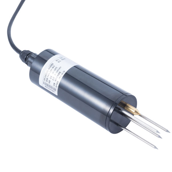
Choose points from the irrigation layout and active root zone. Under drip irrigation, distance from an emitter and sensing depth affect the observed wetting response. A point inside a locally saturated pocket can stop irrigation before much of the zone is supplied; a point beyond the wetted area can continue requesting water despite adequate delivery elsewhere.
Prepare consistent soil contact and avoid air gaps. Mark the position so cultivation and maintenance do not cut the cable. For a permanent point, record depth and position relative to the crop row and emitters. For repeat spot checks, use the same insertion method before comparing values.
Different soil or crop areas may need separate control zones or separate interpretation. Adding several probes does not solve a poor averaging rule. Decide whether each reading is advisory, a representative control input, or an independent condition requiring attention. Keep a questionable point from silently dominating the whole field's irrigation demand.
A shallow point can show an early wetting response while a deeper point helps indicate whether water has reached a lower position. NBL-S-TMSMS profile options provide multiple sensing positions; the standard configuration described for that family uses 10, 20, 30 and 40 cm. Confirm the positions of the offered assembly.
A wet lower layer does not by itself quantify water lost below the root zone. Interpretation needs the soil profile, timing and crop context. Do not program an irrigation rule that assumes every change at a deep point has the same cause.
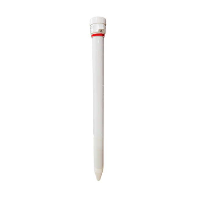
The NBL-S-THR moisture and temperature option illustrates the electrical details that should be fixed before connecting a control set. These values are not shared automatically by a profile sensor, water-potential sensor or USB instrument.
| NBL-S-THR characteristic | Value | Controller implication |
|---|---|---|
| Measurement ranges | Moisture 0-100%; temperature -50 to +100 degrees C | Keep the channel unit and scale consistent with the supplied version. |
| Accuracy and resolution | Moisture +/-3%, resolution 0.1%; temperature +/-0.5 degrees C, resolution 0.1 degrees C | Do not mistake a small displayed step for the complete measurement accuracy. |
| Power | 12-24 V DC; approximately 0.3 W | Check voltage at the installed probe and include all probes in the supply budget. |
| Outputs | RS485, or ordered 4-20 mA or 0-5 V version | Specify the actual interface and receiving input, not an assumed set of simultaneous outputs. |
| Environment | Operating -40 to +80 degrees C; IP68 probe | Protect field joints separately; the measurement range is not the operating limit. |
| Cable | Length and jacket to be specified for the installation | Choose routing and protection for burial, cultivation and enclosure entry. |
For an ordered current-output channel scaled to 0-100% moisture, 8 mA corresponds to 25%. This relationship verifies the declared electrical scaling; it does not make 25% a suitable irrigation threshold. Use the delivered scale and input arrangement, including its fault handling.
For RS485 Modbus RTU integration, verify the device address, serial settings and actual register exchange with the selected PLC or RTU. A soil sensor's field bus does not provide internet access. Any gateway and its remote functions are separate parts of the system.
Use a defined start condition and a distinct stop or completion condition to avoid rapid repeated switching around one value. The difference between those conditions, any persistence period and the permitted irrigation window must be chosen for the site. Do not copy a pair of moisture percentages from a different soil and crop.
Define what happens if no fresh valid reading is available. The answer might be an operator review or a separately approved fallback schedule, not automatically “keep watering” or “never water.” The correct response depends on the crop risk, water availability and protections in the irrigation design.
Also define maximum runtime, unexpected flow, low pressure and manual override where these functions are required. The controller output may need an interposing device and motor protection. A logger relay rating is not permission to connect any pump motor directly.
Set the observation and control timing to the hydraulic response. A probe may not respond immediately after a valve opens, especially at a deeper point. Repeatedly starting new cycles while waiting for a wetting front can overwater the zone. Test the intended sequence rather than evaluating each component separately.
| Observed condition | Useful next check |
|---|---|
| Valve command is active, but measured flow is absent | Investigate valve actuation, isolation, pump and supply pressure; do not extend runtime solely to chase a soil response. |
| Flow continues after the stop command | Inspect the actual valve and hydraulic path under the site's safe procedure; an inactive relay does not establish shutoff. |
| Only the shallow point becomes wet | Review timing, application distribution and sensing positions before changing the deep threshold or declaring water loss. |
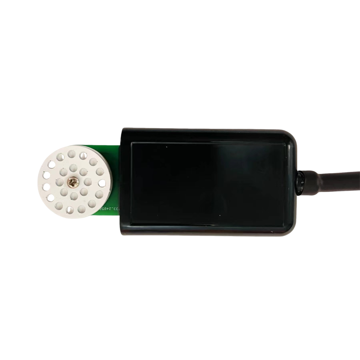
Do not adjust the sensor merely to make its display match an expected valve runtime. If delivery is uneven, investigate emitters, pressure and zone layout. If the field value is implausible, inspect contact, location, supply and acquisition before changing the control limit.
For a quotation, send NiuBoL the crop, soil, irrigation method, zone layout, chosen measurement and existing controller interface. Include sensor locations, cable distances and whether the requirement is monitoring or automatic control. Ask for the sensor, acquisition and any control functions as distinct items so their responsibilities are clear.
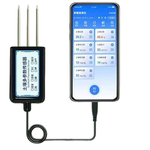
A measurement probe normally needs a compatible controller or interface and an appropriate actuator circuit. Confirm the selected device's functions; an RS485 reading is not a valve-driving output.
No. Water retention and crop response differ. Establish limits for the actual soil, crop and sensing method, and validate the irrigation response before unattended operation.
Only when the averaging rule has a defensible relationship to the zone. Distinct soils or wetting patterns may need separate interpretation, and a failed point should not be averaged into a plausible-looking control value.
No. The output state does not demonstrate valve movement, pressure or delivered flow. Use the appropriate hydraulic feedback and field checks for the system's risk and purpose.
No. They report different quantities and need different interpretation. Check the control method, range, units and field response rather than reusing a VWC threshold.
It identifies the instruments, controller interfaces, hydraulic responsibilities, protections and commissioning work. Compare the same functions rather than a sensor-only price against a complete installed loop.
A smart irrigation control set should connect a defensible root-zone observation to a tested irrigation sequence. Match the sensing method, location and electrical interface first, then verify delivery and abnormal behavior. Automation is useful when the complete loop works, not merely when a dashboard shows a number.
Prev:Rain Gauge Cost: Gauge Only, Interface Upgrade or Complete Station?
Next:Air Temp Sensor Reads High in Sunlight: Check Exposure Before Calibration
Related recommendations
Sensors & Weather Stations Catalog
 Agriculture Sensors and Weather Stations Catalog-NiuBoL.pdf
Weather Stations Catalog-NiuBoL.pdf
Agriculture Sensors Catalog-NiuBoL.pdf
Water Quality Sensor Catalog-NiuBoL.pdf
Related products
 Combined air temperature and relative humidity sensor TDR Soil Moisture & Temperature Sensor for irrigation| RS485 |4-20mA| NBL-S-THR
 Soil pH sensor RS485 soil Testing instrument soil ph meter for agriculture |NBL-S-PH
 Wind Speed sensor Output Modbus/RS485/Analog/0-5V/4-20mA
 Tipping bucket rain gauge for weather monitoring auto rainfall sensor RS485/Outdoor/stainless steel
 Pyranometer Solar Radiation Sensor 4-20mA/RS485


Screenshot, WhatsApp to identify the QR code
WhatsApp number:+8615367865107
(Click on WhatsApp to copy and add friends)

