





— Blogs —
—Products—
 Consumer hotline +8618073152920
WhatsApp:+8615367865107
Address:Room 102, District D, Houhu Industrial Park, Yuelu District, Changsha City, Hunan Province, China
Product knowledge
Time:2026-09-13 12:00:00 Popularity:209
Quick Answer: Surface water automatic monitoring system components include a representative measuring point, sensors, a mounting or sample-delivery arrangement, a data logger, power, communications and practical maintenance access. The first design decision is whether to measure directly in the river or lake or bring water to a station. That choice changes the hydraulic delay, infrastructure, cleaning work and meaning of the recorded data.

A river station can monitor upstream conditions, a tributary input or water leaving a managed reach. A lake station may follow a near-shore intake or conditions at a particular depth. These are not interchangeable duties. A single probe near a bank cannot establish the condition of an entire water body, even when it measures several parameters continuously.
Before selecting surface water automatic monitoring system components, identify the decision the station must support. An intake operator may need warning of a changing source-water condition. A river manager may need to compare a tributary with the main channel. A research team may need a repeatable depth and timestamp. Each purpose leads to a different location and observation schedule.
Inspect the site at more than one water level where possible. A convenient mounting point can become dry in the low season, buried after sediment movement or unsafe to reach during high flow. Record the intended measuring depth, expected level variation and retrieval route. These physical constraints determine whether an otherwise suitable sensor can produce a useful long-term record.
| Design issue | Direct immersion | Pumped station |
|---|---|---|
| Water reaching the sensor | Water surrounding the installed probe | Water conveyed through an intake and tubing |
| Time represented by a reading | Includes sensor response and local mixing | Also includes transport and flow-cell exchange |
| Main physical risks | Debris, changing depth, scour and access | Blocked intake, pump failure, leaks and altered sample conditions |
| Maintenance access | Requires safe probe retrieval | Instruments may be accessible indoors, but intake maintenance remains |
| Typical infrastructure | Mount, cable route and protected electronics | Pump, tubing, flow control, drain and instrument enclosure |
Direct immersion avoids a sample transport line but exposes the sensing point to the river. A pumped arrangement can make maintenance easier and accommodate instruments requiring a controlled flow cell. It does not preserve every parameter automatically: pressure changes, air entry, temperature change, settling and deposits in tubing can affect the sample before measurement.
For dissolved oxygen, avoid introducing air into a comparison sample. For suspended material, consider whether the intake and pipe velocity selectively exclude or deposit particles. For ammonia monitoring, sample residence time and fouling deserve attention alongside the probe itself. A dedicated ammonia nitrogen sensor adds a chemical channel; it does not correct a poorly representative intake.
For a simple example, a 20 m tube with a 10 mm internal diameter contains approximately 1.57 L. At a measured flow of 1 L/min, the nominal tube residence time is about 94 seconds. This is an illustration, not a recommended flow rate. The flow cell, dead spaces, mixing and sensor response add further delay, and a falling pump flow increases it.
Measure the actual flow at the installed operating head rather than using the pump's unrestricted rating. A station that reports every minute may still be observing water drawn several minutes earlier. Record the sampling interval separately from the estimated transport delay; increasing the logging frequency cannot remove hydraulic lag.
Provide a low-flow indication or another validated means of recognizing failed sample delivery. A powered sensor sitting in an isolated chamber may continue returning plausible numbers after the intake stops. The data logger must not present those readings as fresh river observations merely because Modbus communication remains healthy.
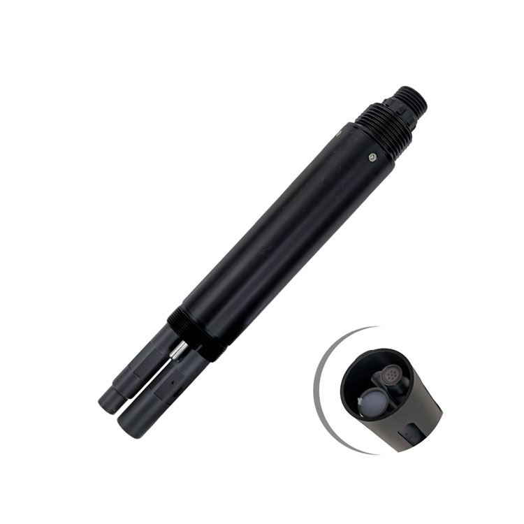
A multi-parameter probe reduces the number of separate installations at one point, but it is only one part of a surface water monitoring station. The NBL-WQ-MPS-5B is a configurable assembly for up to six parameters including temperature. The NBL-WQ-MPS-5A supports configurations of up to eight parameters including temperature. Specify the fitted modules; a product family's possible channels are not a list of channels automatically included in every unit.
| NBL-WQ-MPS-5A platform item | Specification | Station design consequence |
|---|---|---|
| Supply | 12 V DC, +/-5% | Maintain 11.4-12.6 V at the assembly, including cable voltage drop |
| Power | 5 W at 12 V | Include the probe in the power budget; assess other loads separately |
| Digital interface | RS485, Modbus RTU | Use a compatible master and the register map for the supplied configuration |
| Default serial format | 9600 baud, 8 data bits, no parity, 1 stop bit | Match the logger port before testing individual channels |
| Standard cable | 5 m, four-core twisted-pair shielded cable | Plan the junction location; specify jacket suitability for site exposure separately |
| Mechanical support | Lifting ring or 4 NPT mounting arrangement | Support the assembly mechanically, not by its signal cable |
| Cleaning | Adjustable automatic brush cleaning | Allow space for the cleaning mechanism and maintenance access |
These are platform requirements for the 5A assembly, not a common specification for all NiuBoL probes or for the complete cabinet. Confirm the assembled unit's immersion, pressure and environmental limits for the chosen installation. A temperature measurement range alone does not establish the permitted operating temperature of every electronic or mechanical component.
Organic-load investigation may require a separate optical COD channel. Its measurement principle and range must suit the water matrix and the intended interpretation. Treat an online optical result as a method-specific observation; it should not be relabeled as a laboratory result without a suitable comparison and reporting basis.
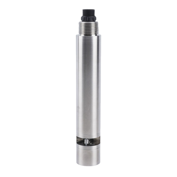
The acquisition chain normally runs from the RS485 sensors to a PLC, RTU or data logger, then through a gateway to the receiving platform. Modbus RTU provides the local exchange of data. It does not by itself provide cellular connectivity, a cloud account, storage or an alarm service. Assign each of those functions to an identifiable component in the station design.
For every installed channel, retain the parameter name, unit, decimal scale, sensor identity and timestamp. Keep acquisition time distinct from server arrival time, especially when a communication outage is followed by a backlog upload. Otherwise, a recovered historical event can appear to be a new incident at the moment the network reconnects.
The MPS-5A register structure includes value and decimal-place information. Its available address map is broader than the modules in any particular assembly. Read only the configured channels and verify their physical presence. An absent or disconnected module can return zero in some circumstances; a numerical zero must not automatically be classified as a valid clean-water reading.
Conductivity is useful for tracking changes in dissolved ionic content and distinguishing some mixing events. It is not a selective measurement of a particular pollutant. Store the selected range and temperature-compensation basis with the channel configuration so that a replacement probe or altered setting does not create an unexplained step in the historical series.
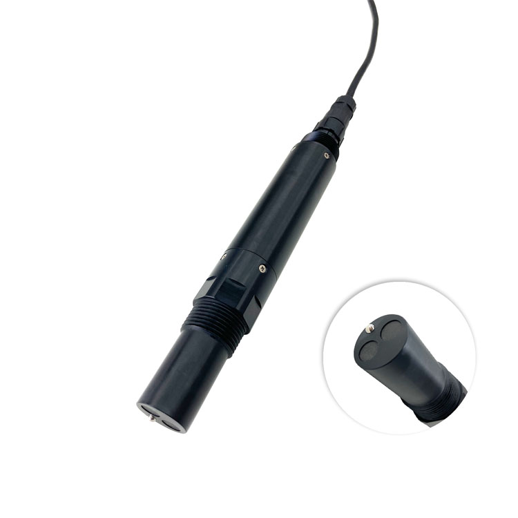
For a bank-mounted station, include the retrieval mechanism, a safe working position and a route for taking the probe out without dragging it through sediment. A protective cage can reduce impact risk, but an enclosure that traps silt or restricts exchange can change the water around the sensors. Inspect the installed arrangement rather than assuming protection always improves measurement.
For a pumped station, separate the duties of the intake screen, tubing, flow cell and sensor cleaner. A brush inside a multi-parameter assembly does not clear a blocked intake or remove deposits from a long sample line. Place isolation and drain points where an operator can service the system without flooding the cabinet or losing control of the sample discharge.
Calculate the power budget from the actual operating schedule. A continuously operating 5 W probe alone accounts for 120 Wh/day, before the logger, modem, conversion losses, heaters or sample pump. This arithmetic is not a complete solar design: usable battery capacity, low-temperature performance, shading and seasonal solar availability still determine the required storage and panel arrangement.
Distinguish a failed communications link from failed measurement. Local storage may preserve data during a network outage, but it cannot recover observations lost because the probe had no power. Check both functions independently. The enclosure also needs suitable cable entries, condensation management and electrical protection; an immersion-rated sensor does not confer the same protection on its external connectors.
Where an optical BOD channel is included, define what the displayed estimate represents and how it will be checked against the site's laboratory method. A continuously available surrogate can help identify change, but its relationship to laboratory BOD depends on the water matrix. That distinction belongs in the monitoring plan before a purchasing decision, not after conflicting results appear.

No. Direct immersion can be suitable when the measuring location is representative and the probe can be mounted and retrieved safely. Pumping is justified by instrument requirements or access constraints, but adds transport delay, sample-handling effects and additional maintenance. Choose it for a specific need rather than as a default component.
It can combine parameters at one location, not combine spatially different water into a representative result. Tributaries, stratified depths and isolated bays may need separate observations. Use preliminary field measurements to decide whether one point adequately answers the monitoring question.
It needs Modbus RTU master functionality and support for the correct addresses, decimal scaling and configured channels. Also verify power delivery and fault handling. An RS485 connector alone establishes neither a complete driver nor correct interpretation of the returned values.
Identify the installed sensor modules, mount or sampling system, logger, power arrangement, communications hardware and commissioning work. For remote sites, distinguish recurring connectivity charges and site works from equipment supply. A bare-probe price is not comparable with an installed river station price.
Set an initial inspection schedule from fouling risk and access constraints, then revise it using deposits, flow loss and verification results. Automatic brushing can reduce fouling at the sensor, but does not eliminate reference checks, intake service or inspection after high-water events.
That depends on the required methods, location rules and quality-control procedures. Continuous collection does not itself establish regulatory acceptance. Identify the reporting requirements first and decide which channels support operational warning, which require laboratory confirmation and which are accepted for the intended submission.
A reliable surface water monitoring station starts with a defensible measuring point and a clear route from that water to a recorded observation. NiuBoL sensor selection should follow the sampling decision, channel requirements and maintenance access. For a project configuration, provide the site layout, water-level variation, required parameters, power availability and preferred data connection; those details determine which components are necessary and which would add cost without improving the measurement.
Prev:Smart Aquaculture Water Quality Monitoring System: Pond Project Selection Guide
Next:ORP Sensor for Water Quality: Reference Scale and Data Integration
Related recommendations
Sensors & Weather Stations Catalog
 Agriculture Sensors and Weather Stations Catalog-NiuBoL.pdf
Weather Stations Catalog-NiuBoL.pdf
Agriculture Sensors Catalog-NiuBoL.pdf
Water Quality Sensor Catalog-NiuBoL.pdf
Related products
 Combined air temperature and relative humidity sensor
 TDR Soil Moisture & Temperature Sensor for irrigation| RS485 |4-20mA| NBL-S-THR
 Soil pH sensor RS485 soil Testing instrument soil ph meter for agriculture |NBL-S-PH
 Wind Speed sensor Output Modbus/RS485/Analog/0-5V/4-20mA
 Tipping bucket rain gauge for weather monitoring auto rainfall sensor RS485/Outdoor/stainless steel
 Pyranometer Solar Radiation Sensor 4-20mA/RS485


Screenshot, WhatsApp to identify the QR code
WhatsApp number:+8615367865107
(Click on WhatsApp to copy and add friends)

