





— Blogs —
—Products—
 Consumer hotline +8618073152920
WhatsApp:+8615367865107
Address:Room 102, District D, Houhu Industrial Park, Yuelu District, Changsha City, Hunan Province, China
Product knowledge
Time:2026-08-12 09:08:00 Popularity:271
Quick Answer: A conductivity-based TDS measurement instrument can show a step change after its conversion coefficient is changed even when the water's conductivity is unchanged. Preserve conductivity, temperature, conversion settings and the change time. Do not interpret the whole TDS history as one comparable series without checking how each period was calculated.
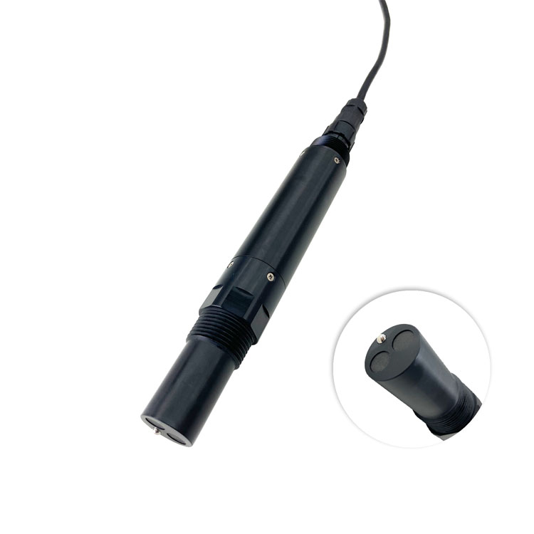
A TDS measurement instrument commonly estimates dissolved solids from electrical conductivity. The NiuBoL NBL-WQ-EC supports a configurable TDS coefficient, with a listed default of 0.64. That coefficient is part of the reported result, not a second independent measurement of dissolved mass.
Consider an illustrative conductivity value of 600 uS/cm. A coefficient of 0.64 gives an estimated 384 mg/L; a coefficient of 0.50 gives 300 mg/L from the same conductivity. This is a calculation example, not a field result or a recommendation to use 0.50. A lower display after the setting change does not establish improved treatment.
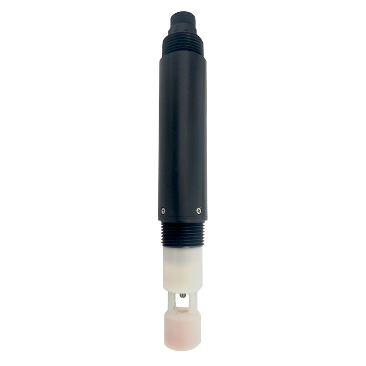
The salinity probe below is a separate configuration with a different reporting purpose. Neither its photograph nor a common mg/L display makes salinity and conductivity-derived TDS interchangeable. Identify the quantity and calculation used by each instrument before comparing periods or sites.
| Record | Why retain it | What can go wrong without it |
|---|---|---|
| Conductivity with unit and compensation basis | Provides the measured basis behind the TDS conversion | A coefficient change can be mistaken for a salt change |
| Water temperature | Helps interpret temperature-related differences | Compensated and uncompensated observations may be mixed |
| TDS coefficient and effective change time | Identifies which conversion applied to each period | The display history becomes impossible to reproduce reliably |
| Reported TDS and configuration version | Preserves what operators saw when making decisions | A later recalculation can silently rewrite the apparent event |
These are acquisition-system requirements. Do not assume the probe stores a complete configuration history or automatically tags every record with the coefficient. Confirm which registers are available and what the logger, PLC or platform will save. Where the receiver performs the conversion, record its configuration change as well as any probe change.

The BOD probe above measures a different water-quality indicator; it is not the EC instrument whose coefficient is being changed. The following values apply to the NBL-WQ-EC conductivity family. Specify the selected range rather than assigning every available span to one delivered probe.
| EC family specification | Value | Consequence for TDS records |
|---|---|---|
| Conductivity ranges | 0-20.00 uS/cm; 0-200.0 uS/cm; 0-5000 uS/cm; 0-200.0 mS/cm | Record the ordered range and unit |
| Accuracy | +/-1% FS | A new TDS coefficient does not improve EC accuracy |
| Listed derived TDS ranges | 0-10, 0-100 or 0-3000 mg/L for the respective first three versions | Confirm availability and mapping for the ordered configuration; high-range TDS requires confirmation |
| Temperature / pressure | 0-50 C; <0.6 MPa | Keep the actual sample within operating limits |
| Supply / consumption | 12-24 VDC +/-10%; 0.2 W at 12 V | Size the receiver and station separately |
| Output / protection | RS485 Modbus RTU / IP68 | Verify both raw channel and derived-value decoding |
| Materials / mounting / cable | ABS, default SUS316L or PVC by configuration; 3/4 NPT; standard 5 m | Confirm the delivered material and cable jacket for the water |
Do not use a conversion adjustment to hide an EC calibration problem. Verify the conductivity channel with a suitable standard and check its temperature treatment first. The reason for a different coefficient should concern the intended water and reporting method, not merely a desire to make two unrelated displays agree.
Before changing the setting, save the old configuration and representative EC, temperature and TDS observations. Record why the change is being made and which alarms, displays or reports use TDS. Afterward, read the setting back where supported and verify the receiver's calculation with a known example.
Mark the effective change in the history. Retain original reported values; if a normalized series is calculated for comparison, label it separately with the coefficient and method used. Recalculation is only defensible when the necessary EC and temperature basis were retained. Do not reconstruct missing observations from an assumed default.
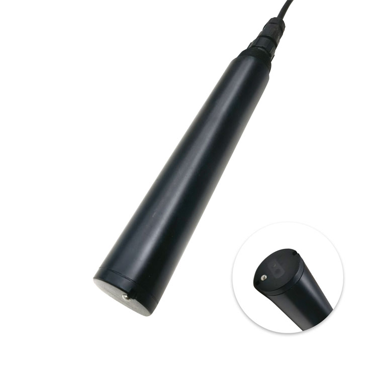
Turbidity, pictured above, represents suspended material rather than dissolved solids. An ammonium-specific measurement below also cannot reconstruct a missing EC record. Other channels may help investigate an event, but they do not recover the numerical basis of an undocumented TDS conversion.
An unchanged TDS threshold can mean a different conductivity threshold after a coefficient change. Review the operating purpose and the reference basis before leaving alarms active under the new setting. Test the receiving system's interpretation without deliberately creating an unacceptable process condition.
For an enquiry, provide the required EC and TDS ranges, water composition, existing controller, calculation location and history requirements. Ask NiuBoL for the applicable registers and configuration procedure, and ask the integrator which settings and changes the selected logger will actually retain.
No. It changes the estimated TDS derived from the same EC. Establish whether conductivity or water composition changed independently before interpreting the new number.
Do not assume universal suitability. Conversion depends on the intended water and reporting basis. Evaluate it against the project's requirements rather than treating a default as a laboratory result.
Preserve the original reported series. A separately labeled recalculation may support comparison when sufficient EC and configuration information exists, but it should not erase what operators originally received.
No. Modbus provides a communication method. The selected acquisition system must record the relevant settings and changes; confirm that function explicitly.
No. EC calibration and the TDS conversion answer different questions. Verify EC first, then assess whether the conversion is appropriate for the intended water.
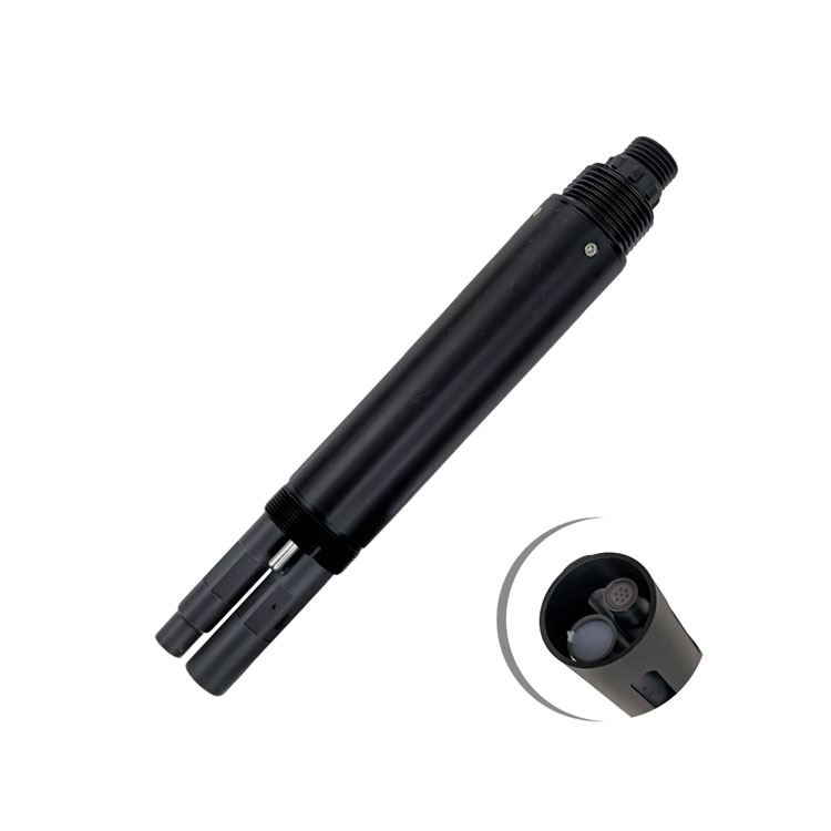
No. The optical DO probe below measures oxygen. A plausible oxygen trace does not establish that a TDS coefficient or its historical application is correct.
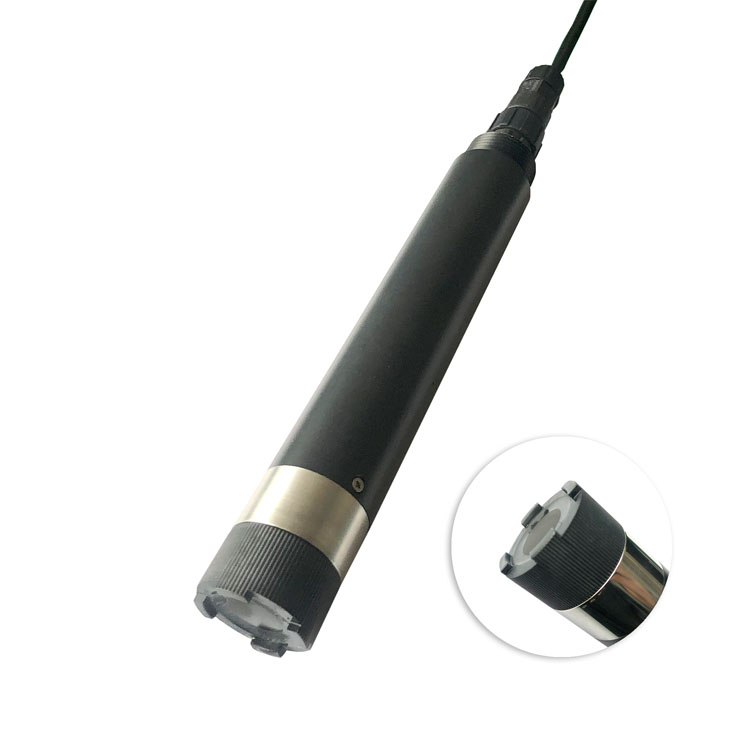
Specify a TDS measurement instrument together with its calculation and record-keeping requirements. Keeping EC, temperature, coefficient and change time makes a configuration step distinguishable from a process event. It also prevents a software adjustment from silently changing the meaning of a treatment alarm.
Prev:Turbidity Measuring Instrument Selection Guide
Next:TDS and pH Tester for Blended Water: Verify the Final Mixture
Related recommendations
Sensors & Weather Stations Catalog
 Agriculture Sensors and Weather Stations Catalog-NiuBoL.pdf
Weather Stations Catalog-NiuBoL.pdf
Agriculture Sensors Catalog-NiuBoL.pdf
Water Quality Sensor Catalog-NiuBoL.pdf
Related products
 Combined air temperature and relative humidity sensor
 TDR Soil Moisture & Temperature Sensor for irrigation| RS485 |4-20mA| NBL-S-THR
 Soil pH sensor RS485 soil Testing instrument soil ph meter for agriculture |NBL-S-PH
 Wind Speed sensor Output Modbus/RS485/Analog/0-5V/4-20mA
 Tipping bucket rain gauge for weather monitoring auto rainfall sensor RS485/Outdoor/stainless steel
 Pyranometer Solar Radiation Sensor 4-20mA/RS485


Screenshot, WhatsApp to identify the QR code
WhatsApp number:+8615367865107
(Click on WhatsApp to copy and add friends)

