





— Blogs —
—Products—
 Consumer hotline +8618073152920
WhatsApp:+8615367865107
Address:Room 102, District D, Houhu Industrial Park, Yuelu District, Changsha City, Hunan Province, China
Product knowledge
Time:2026-08-17 09:05:00 Popularity:260
Quick answer: A TDS water sensor used for cooling-tower blowdown should be assessed as part of a conductivity-based measurement and control channel. The NiuBoL NBL-WQ-EC measures conductivity and supplies estimated TDS where the range supports it. Confirm which value the controller actually uses. The water-treatment specialist must set the operating limit; a generic TDS number does not establish acceptable scale, corrosion or biological conditions.
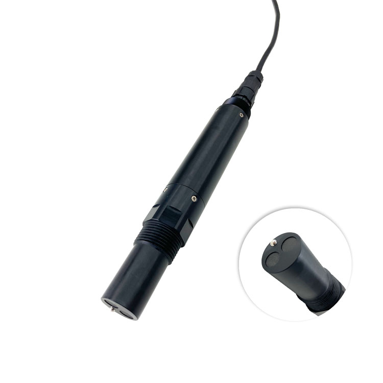
Evaporation leaves dissolved solids in recirculating tower water, while blowdown removes some concentrated water for replacement with make-up water. The U.S. Department of Energy cooling-tower guidance describes conductivity-based blowdown control and calls for limits selected with a water-treatment specialist.
A controller configured in uS/cm should receive verified conductivity, not an estimated mg/L value relabeled as conductivity. If the site reports TDS as well, retain the coefficient and the reporting basis. Changing that coefficient should not silently change a conductivity-based operating rule.
The base pH probe below is a separate process measurement. Conductivity does not replace pH, water chemistry testing or checks required by the treatment program.
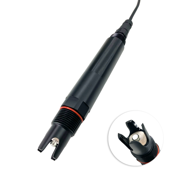
| NBL-WQ-EC item | Specification | Cooling-water check |
|---|---|---|
| Conductivity ranges | 0-20.00, 0-200.0 or 0-5000 uS/cm; or 0-200.0 mS/cm | Select for normal operation and expected excursions, not the product label alone |
| Accuracy | Conductivity +/-1% F.S.; temperature +/-0.3 C | For the 5000 uS/cm span, 1% F.S. equals 50 uS/cm, not 1% of every reading |
| TDS | Calculated from conductivity; configurable coefficient, default 0.64; range support varies | Keep the control variable and any display conversion distinguishable |
| Temperature compensation | Integrated Pt1000 and automatic compensation | Compare make-up and recirculating records on a compatible temperature basis |
| Supply / consumption | 12-24 VDC +/-10%; 0.2 W at 12 V | Size controller, actuator and communications loads separately |
| Output | RS485 Modbus RTU; default 9600, N, 8, 1 | Confirm registers, decimals, units and stale-data handling |
| Working conditions | 0-50 C; pressure below 0.6 MPa | Verify actual sample temperature and pressure, including transients |
| Protection / mounting / cable | IP68; 3/4-inch NPT; standard 5 m cable | Confirm wetted materials, cable jacket and service access for treated water |
Verify that water at the sensing point remains within the 0-50 C operating range. If sample conditioning is necessary, assess its effect on representativeness and response. Check the selected wetted materials against the treatment chemicals; IP68 describes ingress protection, not chemical or high-temperature compatibility.
The PH-4S below is an alternative pH instrument with its own operating limits. Its pressure or temperature allowance must not be borrowed for the EC channel.
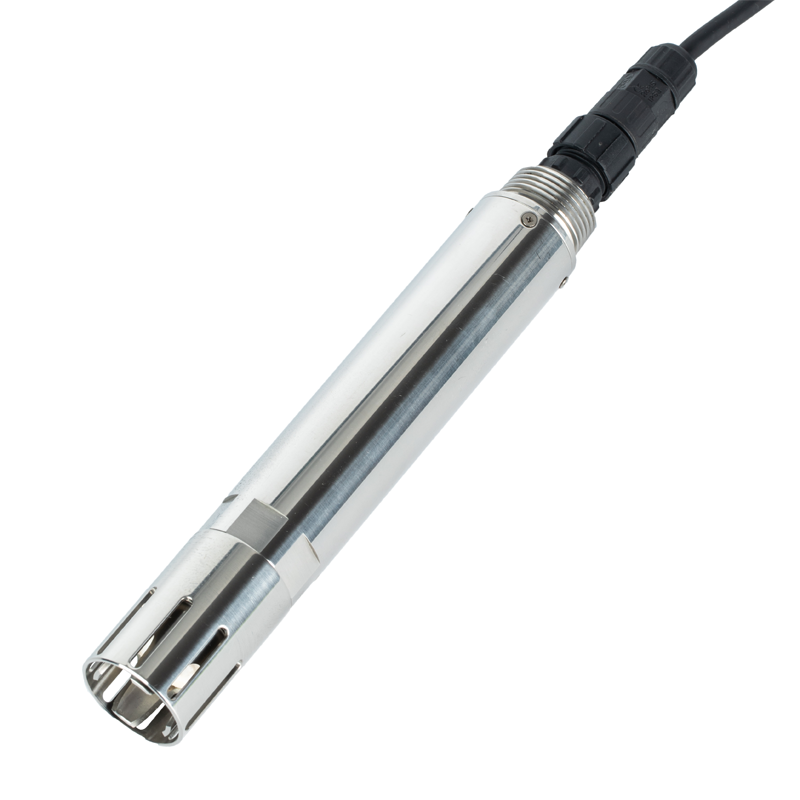
The EPA WaterSense cooling-tower guide uses the ratio of blowdown-water conductivity to make-up-water conductivity when reviewing cycles of concentration. Use comparable measurements and review the result against the actual treatment program. As a hypothetical calculation, 3000 uS/cm divided by 1000 uS/cm gives a ratio of 3; it is not a recommended operating target.
If the make-up source changes, retain that event and compare the new baseline rather than assuming a higher tower reading always means the blowdown valve has failed. Conductivity cannot identify which individual ions have changed. Where hardness, silica or another constituent limits operation, retain the required chemistry analysis.
The optical DO probe below measures dissolved oxygen separately. It does not validate the EC conversion or establish that a treatment program remains effective.
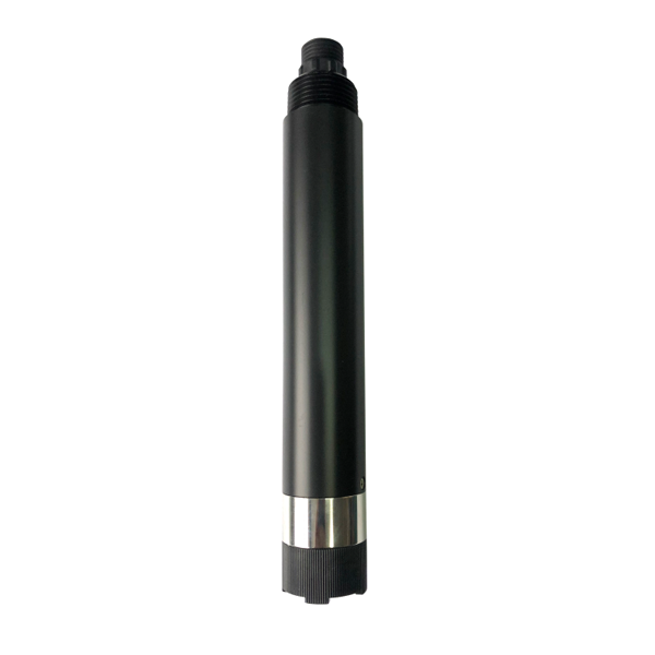
At commissioning, compare a suitable reference with the installed channel under matched conditions. Then verify raw Modbus data, decoded EC and the controller's displayed value. Check the sampling location and keep electrodes free of deposits; do not recalibrate around a blocked or stagnant sample path.
During an approved controlled test, record the command to open the valve, the actual discharge indication and the subsequent conductivity response. A commanded-open valve does not prove water left the system. Verify return to normal, maximum permitted operation and the response to unavailable data in the chosen controller.
Record make-up and blowdown flow where the project provides those measurements. These records help distinguish a measurement issue from water-balance or valve behavior. The EC probe does not itself provide those flows, a relay output or a complete treatment controller.
The EC-S salinity instrument below reports a different quantity. Do not substitute a PSU record for the EC channel without reviewing the entire calculation and control basis.
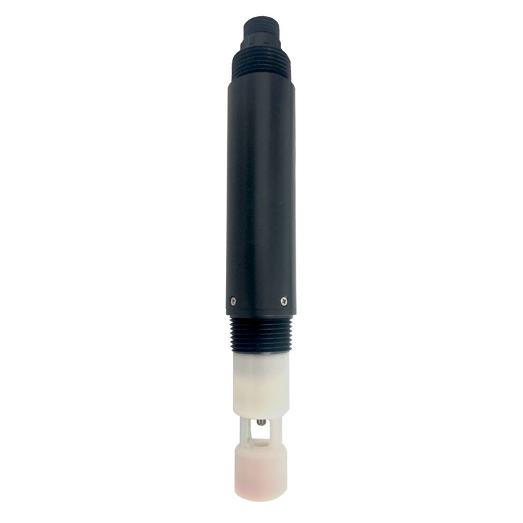
The listed NBL-WQ-EC supplies measurement data. A compatible controller and suitable actuator interface are required, with the operating sequence verified for the site.
No. Make-up chemistry, treatment, equipment and operating conditions determine the acceptable limit. Obtain the treatment specialist's target rather than copying a generic value.
No. It supports concentration review but does not identify specific ions or all treatment risks. Keep the water analyses required for the actual program.
Check actual discharge, make-up supply, measurement location, deposits and configuration before attributing it to sensor drift. A command record alone does not demonstrate the hydraulic response.
Send normal and maximum EC, sample temperature and pressure, treatment chemicals, make-up source, sample layout and controller details. Ask NiuBoL to review the range, materials and interface rather than assuming a sensor-only replacement completes the loop.
No. The separate NBL-WQ-BOD-4S pictured below uses fluorescence for an organic-load-related estimate. It does not measure conductivity or provide a direct microbial count. Do not add it as an assumed replacement for the treatment program's required tests.

A cooling-tower conductivity channel is useful when its range, compensation, sampling and valve response are verified together. Keep calculated TDS, pH and other measurements separate, and use site-specific water-treatment requirements to define the operating limits.
Prev:Water Turbidity Meter for Intermittent Discharge: Capture Each Release
Next:Online COD BOD TSS pH Analyzer: Four Channels, Different Methods
Related recommendations
Sensors & Weather Stations Catalog
 Agriculture Sensors and Weather Stations Catalog-NiuBoL.pdf
Weather Stations Catalog-NiuBoL.pdf
Agriculture Sensors Catalog-NiuBoL.pdf
Water Quality Sensor Catalog-NiuBoL.pdf
Related products
 Combined air temperature and relative humidity sensor
 TDR Soil Moisture & Temperature Sensor for irrigation| RS485 |4-20mA| NBL-S-THR
 Soil pH sensor RS485 soil Testing instrument soil ph meter for agriculture |NBL-S-PH
 Wind Speed sensor Output Modbus/RS485/Analog/0-5V/4-20mA
 Tipping bucket rain gauge for weather monitoring auto rainfall sensor RS485/Outdoor/stainless steel
 Pyranometer Solar Radiation Sensor 4-20mA/RS485


Screenshot, WhatsApp to identify the QR code
WhatsApp number:+8615367865107
(Click on WhatsApp to copy and add friends)

