





— Blogs —
—Products—
 Consumer hotline +8618073152920
WhatsApp:+8615367865107
Address:Room 102, District D, Houhu Industrial Park, Yuelu District, Changsha City, Hunan Province, China
Product knowledge
Time:2026-09-16 14:00:00 Popularity:243
Quick Answer: A wastewater treatment plant online monitoring system retrofit should be purchased around the equipment being retained, the interfaces being changed and the operating conditions during cutover. Define those boundaries before comparing offers. New probes must suit the water and work with the receiving system, while installation and commissioning must preserve the plant's required observations and approved control arrangements.
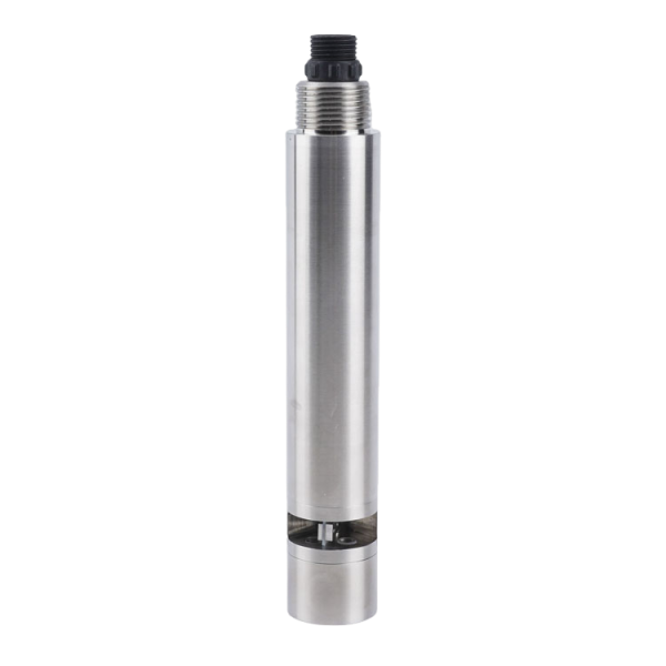
A monitoring upgrade does not necessarily require a new cabinet, controller and platform at every point. Existing power, PLC capacity, cable routes and operator displays may remain useful. Equally, a working display may conceal obsolete interfaces or inaccessible supports. Survey the installed arrangement rather than assuming that every old component must be replaced or that every available component can be reused.
Mark each item as retained, replaced, modified or newly supplied. Identify the affected plant tag and physical location. A sensor replacement at the final outlet and a new measuring point in an aeration basin are different work packages even if the instruments come from the same supplier.
Resolve measurement purpose before detailing the retrofit. An optical COD probe can add an operational trend, but it does not automatically fulfill a requirement for a particular laboratory or analytical method. Confirm the intended result before spending money on a mounting arrangement or software driver for an unsuitable instrument.
| Existing item | Question before reuse | Purchasing consequence |
|---|---|---|
| PLC and input modules | Which ports, functions and application changes are available? | Specify any interface module and programming work rather than buying an unnecessary second controller |
| Power supply | What voltage reaches the instrument under load? | Add suitable regulation or distribution changes where the new model requires them |
| Probe holder or sample circuit | Does it fit the new geometry and provide representative water? | Price mechanical changes separately from probe supply |
| Cable and junctions | Are conductor arrangement, shielding, sealing and condition suitable? | Do not assume the old cable is reusable because its length is sufficient |
| Display and historian | Can they preserve channel identity, units and invalid states? | Include tag changes and verification in the integration work |
A description such as multi-parameter monitoring package leaves important choices open. Identify the point, fitted measurements, normal and credible upset range, sample conditions and required use of the data. The supplier can then distinguish a probe-only delivery from work needed to make that point operational.
Where several parameters share one location, a combined assembly may simplify the physical installation. Where the parameters belong in different tanks, list separate points. For selecting those locations and instruments, use the wastewater treatment station instrument guide. The purchase schedule should carry the resulting tags and configurations rather than repeat a generic channel list at every location.
A conductivity replacement illustrates why range belongs on the line item. Replacing a low-range channel with a much wider range can change useful uncertainty near the operating value. Preserve the engineering unit and compensation basis as well as the physical fitting. A reading that still appears on the screen is not sufficient evidence of an equivalent replacement.
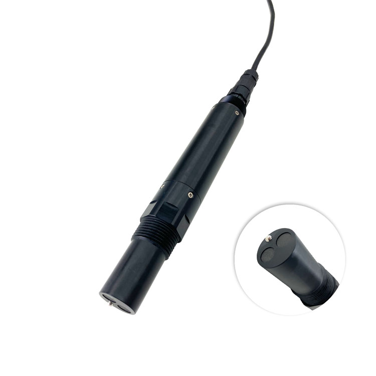
An existing 4-20 mA input does not directly read a digital-only RS485 probe. Conversely, an RS485 connector does not prove that a controller supports Modbus RTU master operation or the required data format. Identify the exact receiving hardware and software, then assign any conversion, port expansion and programming work to the appropriate contractor.
Keep a mapping from the old plant tag to the new device and host tag. Record changes in unit, scale, range and sample location. If the parameter or method changes, do not conceal that change by retaining an old label that implies equivalence. A historical trend needs a clear replacement date and configuration record.
For an online optical BOD channel, identify the reported estimate and its validated relationship with the wastewater. Do not reuse a laboratory BOD5 label merely to avoid changing a display. Method identity affects what operators and report readers can infer from the result, even when both values use mg/L.

A factory demonstration can check wiring and decoding, but it does not reproduce every wastewater matrix. Separate the controlled instrument check from comparison in the actual water. Agree which observations establish a site relationship and which independent observations will be used to assess it. The same samples should not be presented as both calibration data and independent proof.
Define how sampling time and location will match the installed point. An outlet sample collected after a delay may not represent the water that produced an earlier online peak. For pumped systems, include transport and cell turnover. Where the water changes quickly, record the uncertainty in the comparison rather than assigning every disagreement to the probe.
Keep deviations visible. Record the reading before an adjustment, the reason for adjustment and the subsequent check. Repeatedly changing calibration until one laboratory number matches can hide a sampling problem or a changed optical relationship. Acceptance should use a parameter-specific criterion suitable for the intended decision, not one percentage applied to every channel.
For solids measurements, distinguish a turbidity result from suspended-solids mass concentration. A TSS probe needs comparison with the actual particles and an appropriate laboratory result. Moving a sensor from effluent to mixed liquor changes the duty; a unit conversion alone does not establish that the old range or calibration remains suitable.

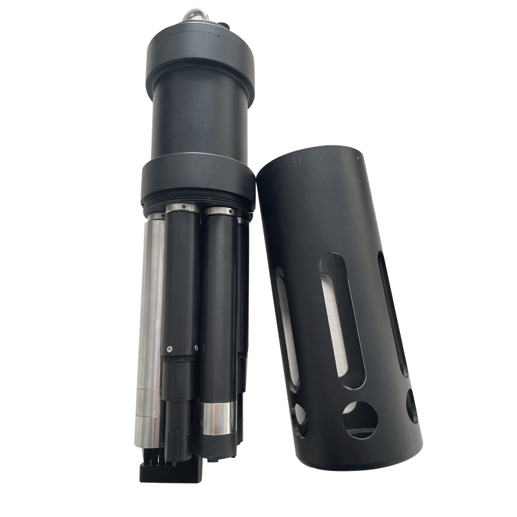
The NiuBoL NBL-WQ-MPS-5A is one option for selected co-located channels, not a complete plant-wide control system. Its requirements show why replacement compatibility must be assessed at model level. In particular, its supply differs from that of several standalone probes.
| MPS-5A item | Specification or option | Retrofit check |
|---|---|---|
| Capacity | Up to eight parameters including temperature | List the actual installed modules; capacity is not a promise that every option is included |
| pH option | 0-14 pH; +/-0.1 pH; 0.01 pH resolution | Check the required measurement tolerance rather than the old display's decimal places |
| ORP option | -1500 to +1500 mV; +/-6 mV | Retain negative values and the defined reference convention in the host |
| Supply | 12 V DC +/-5% | A retained 24 V rail needs a suitable regulated supply arrangement; check voltage at the assembly |
| Consumption | 5 W at 12 V | Assess cleaner demand and the other loads before approving the existing supply |
| Output | RS485 Modbus RTU | Verify master support, channel decoding and the supplied configuration |
| Cable | 5 m standard shielded cable | Approve route, terminations and any extension; confirm jacket compatibility |
| Cleaning and support | Adjustable automatic brush; lifting ring or 4 NPT mounting | Check the retained holder for fit, cleaner clearance and practical retrieval |
Confirm environmental and immersion limits for the complete ordered assembly. Do not transfer a standalone probe's pressure rating to the combined body. Where one assembly is removed for service, several channels can become unavailable together; the operating plan needs to recognize that shared interruption.
Bench-test the new acquisition path before the installation window where practical. Verify power, device identity, units and the intended host tags. Keep configuration writes controlled so a test does not alter unrelated operating channels. Detailed local checks are covered in the bus mapping and recovery guide.
Before disconnecting an operating instrument, agree the site's temporary observation and control arrangements. A process that depends on that channel may need an approved alternative or a planned outage. Do not improvise a replacement value or connect two active masters to one serial bus in an attempt to retain both systems.
Where side-by-side observation is feasible, use it to investigate differences, not to force the new sensor to reproduce an unverified old bias. Record which instrument is authoritative during the comparison. Set a return route if the replacement fails the required checks, including the configuration needed to restore the retained equipment.
After cutover, inspect a fresh stored observation and the relevant operator display. Test the agreed unavailable-data and alarm behavior without deliberately creating an unsafe process condition. A value visible immediately after connection may be cached; confirm that new acquisition is actually occurring.
Assign responsibility for supports, sample fittings, power changes, host programming and site checks. An excluded task is not necessarily missing from the project if the owner or another contractor explicitly provides it. It becomes a risk when everyone assumes another party has included it.
Separate equipment readiness from site readiness in the schedule. Correctly delivered probes cannot be commissioned into unfinished holders or an unresolved sample drain. Confirm access, installed power and the receiving application before arranging the final test visit. Request current delivery commitments for the selected models and options rather than assuming one lead time covers every configuration.
For a NiuBoL proposal, provide the marked-up existing-system drawing, retained equipment list, measuring duties and required installation window. Identify any mandatory method or project documentation separately. This allows the proposed instruments and integration work to be evaluated against a real retrofit rather than an undefined new station.
No. Retain it when its interfaces, capacity and application can support the required measurements. Identify any additional hardware and programming first. Replacement is justified by a demonstrated limitation, not simply by the age of the sensors being changed.
Only after checking fit, water exposure, support loads, electrical requirements and condition. A matching thread or cable length does not establish complete compatibility. Resolve any changes on the installation drawing before releasing the hardware order.
They must cover the same measurement duties and identify the work supplied by others. Separate probe supply from mounting, interfaces and commissioning. For pricing detail, refer to the equipment price and quotation-scope guide.
No. It can verify the bench data path, while site measurement, installed hydraulics and operating behavior remain to be checked. Agree which tests belong before delivery and which require the actual wastewater and receiving system.
Not necessarily. Method, location, instrument condition and compensation can differ. Compare against the agreed reference and investigate the difference. Do not calibrate a replacement solely to reproduce an old instrument whose accuracy has not been established.
Define the responsible contact, temporary monitoring arrangement and conditions for a repeat test or return to the previous setup. Keep open items linked to the affected plant tags. Do not present an incomplete measuring point as accepted because the supplied hardware powers on.
A wastewater treatment plant online monitoring system retrofit should preserve useful infrastructure while making measurement and interface changes explicit. Specify NiuBoL instruments against the selected duties, verify the complete replacement path and agree the cutover conditions. That gives procurement, installation and operations teams the same definition of a working measuring point.
Prev:Sludge Concentration vs MLSS: Measurement Difference and Sensor Selection
Next:Wastewater Treatment Station Water Quality Instruments: Selection Guide
Related recommendations
Sensors & Weather Stations Catalog
 Agriculture Sensors and Weather Stations Catalog-NiuBoL.pdf
Weather Stations Catalog-NiuBoL.pdf
Agriculture Sensors Catalog-NiuBoL.pdf
Water Quality Sensor Catalog-NiuBoL.pdf
Related products
 Combined air temperature and relative humidity sensor
 TDR Soil Moisture & Temperature Sensor for irrigation| RS485 |4-20mA| NBL-S-THR
 Soil pH sensor RS485 soil Testing instrument soil ph meter for agriculture |NBL-S-PH
 Wind Speed sensor Output Modbus/RS485/Analog/0-5V/4-20mA
 Tipping bucket rain gauge for weather monitoring auto rainfall sensor RS485/Outdoor/stainless steel
 Pyranometer Solar Radiation Sensor 4-20mA/RS485


Screenshot, WhatsApp to identify the QR code
WhatsApp number:+8615367865107
(Click on WhatsApp to copy and add friends)

