





— Blogs —
—Products—
 Consumer hotline +8618073152920
WhatsApp:+8615367865107
Address:Room 102, District D, Houhu Industrial Park, Yuelu District, Changsha City, Hunan Province, China
Product knowledge
Time:2024-10-02 20:35:50 Popularity:3271
Weather station parts include shields, enclosures and supports with different roles. A radiation shield helps an air sensor measure the surrounding atmosphere; an equipment cabinet protects suitable electronics and connections; a mast holds instruments at their intended positions. Select these parts together, but do not enclose every sensor in the same box or treat one protection rating as a specification for the whole station.

A weather station observes atmospheric conditions through sensors connected to acquisition equipment. Wind, air temperature, humidity, pressure and rainfall are common channels; radiation, soil and other instruments are selected for particular applications. Their physical exposure requirements differ, so the appropriate protection is not the same for every part.
A rain collector needs precipitation to enter its opening. Wind cups and a vane need clear movement and suitable wind exposure. An air-temperature and humidity element needs ventilation through a suitable shield. Putting those instruments in a sealed cabinet would change or prevent the observations, even if the electronics remained dry.
| Weather station part | What it does | What it must not prevent |
|---|---|---|
| Air-sensor radiation shield | Reduces direct radiative exposure while allowing air exchange. | Representative airflow around the sensing elements. |
| Logger enclosure | Houses compatible acquisition equipment, terminals and power components. | Permitted equipment temperatures, cable access and any specified antenna arrangement. |
| Mast and crossarm | Support instruments at defined positions. | Wind exposure, collector access and an unobstructed radiation measurement plane. |
| Solar panel and bracket | The panel supplies charging energy; the bracket holds it at the selected position. | The observation area of neighboring sensors. |
| Cable entries and supports | Provide suitable routing, termination and strain relief. | The intended environmental protection and instrument movement. |
A complete component list is useful, but this physical distinction is what prevents a common installation error: choosing a larger cabinet and assuming that it solves every exposure problem. For the broader equipment architecture, see weather station components and their connections.
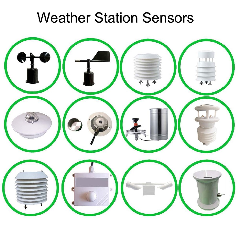
The NiuBoL NBL-W-LBTH combines air temperature, relative humidity and atmospheric pressure in a louvered assembly. Its shield is part of the sensing arrangement. Keep the air paths open and follow its installation requirements rather than adding a tightly fitted plastic cover to improve its appearance.
A location behind a wall may be shaded but poorly represent the air the project intends to observe. The enclosure wall, a heat-producing display or a power device can also influence nearby temperature measurements. Select the sensor position for the observation, then arrange protection and cable routing around it.
Inspect the completed assembly for packing material, labels or cable bundles obstructing the louvers. Avoid attaching unrelated equipment to the shield. These are physical checks an installer can perform before interpreting an unexpected temperature or humidity value as an electronic sensor fault.
The data logger belongs in an arrangement appropriate to its own rating. The TG462/TG462S acquisition family is rated IP30 and is intended to be installed in a suitable protective cabinet for outdoor weather-station use. A weatherproof sensor connected to it does not make the logger weatherproof.
| Example item | Relevant specification | Installation consequence |
|---|---|---|
| TG462/TG462S logger | IP30; operating temperature -35 to +75 C | Provide suitable outdoor protection and assess the conditions inside the cabinet. |
| NBL-W-LBTH | DC 12-24 V; temperature, RH and pressure measurements | Keep its louvered sensing assembly exposed to the intended air, not sealed inside the cabinet. |
| NBL-W-SS wind speed sensor | IP65; output depends on ordered version | Preserve rotor clearance and use the correct acquisition input. |
| NBL-W-DS wind direction sensor | IP65; output depends on ordered version | Preserve vane travel and retain its direction reference. |
For the wind instruments, use the NBL-W-SS and NBL-W-DS protection ratings above. Do not extend those ratings to every connector, cable joint or other sensor on the mast. The finished installation needs suitable entries and terminations as well as appropriately rated individual devices.
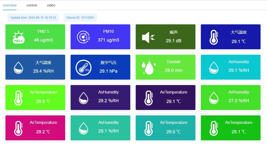
A display or remote dashboard can show whether the logger is communicating, but it cannot demonstrate that the cabinet is dry or that a shield remains ventilated. Include inspection of seals, entries and airflow paths in the installation check. The illustrated display is an example, not a specification of every delivered software function.
RS485 Modbus RTU also describes a data connection, not environmental protection. Match the selected device's serial settings and receiver, and protect the terminations for the site. An analog or pulse version needs the corresponding logger input; it does not become a serial instrument by sharing the cabinet with one.
A solar power assembly can include a panel, charging controller and compatible battery. These are separate parts with their own installation requirements. A panel photograph does not establish that the battery, charge controller or required protection devices are included in an offer.
Allow space for the selected power components without crowding the logger terminals or blocking the door. Assess battery and controller temperature limits separately from the logger's ambient range. A cabinet in direct sun can develop different internal conditions from the air measured outside; its size alone does not establish acceptable operating temperatures.

The panel bracket must suit the panel and keep it clear of the measurements. A panel or cable crossing above a pyranometer can shade it; a panel placed beside a rain collector can affect exposure. Review these relationships in the assembled layout rather than selecting each bracket in isolation.
Power-system sizing is a separate decision from choosing the protective box. Use the actual station load and site conditions. The related solar versus mains power guide explains that choice without treating a standard panel and battery as suitable for every installation.
The NiuBoL weather station mounting bracket has 2 m and 3 m options. The 3 m option uses 1.8 m and 1.2 m sections. These dimensions describe the offered support; they do not prove that every mounted sensing point has the same height or meets every observation method.
Show the position of each instrument, the crossarm orientation and the attachments on the installation drawing. A taller pole does not automatically provide a stronger structure. The foundation, fasteners and structural suitability must be assessed for the actual equipment and site; do not infer a wind-load rating from a product photograph.

Keep cable weight off sensor terminals and moving parts. Route cables so that a service operation does not pull on a neighboring instrument. Where a direction sensor must be removed, retain an identifiable orientation reference on the support so it can be restored deliberately rather than aligned by eye.
Physical support also affects the observation itself. A vibrating attachment can disturb an instrument; a new crossarm can obstruct another measurement. Check the assembled geometry after adding an accessory instead of accepting the addition solely because its clamp fits the mast.
A weather station outdoor protective box should be selected around its contents, cable entries, service access and declared protection. Confirm the actual material and rating for the supplied option. The photographs show example enclosures, not one universal dimension or protection specification for every project.
Use entries and fittings appropriate to the cables and required protection. An unused open hole, an unsuitable cable gland or a damaged door seal can defeat the intended assembly. Do not drill arbitrary ventilation holes to solve heat problems; assess a suitable enclosure and any approved ventilation arrangement instead.

Lightning and surge protection need their own site design. An enclosure, lightning rod or wireless modem is not, by itself, a complete protective system. Installation and earthing work should follow the site's approved electrical and structural requirements and be performed by qualified personnel.
When requesting weather station parts from NiuBoL, send the instrument list, logger model, proposed support layout and cable-entry information. For an existing station, include clear photographs and dimensions of the parts being retained. This makes a box, bracket or shield request specific enough to assess without guessing compatibility from appearance.
Not when the requirement is to measure the surrounding outdoor air. The cabinet can have a different temperature and humidity from that environment. Install the atmospheric sensing assembly with its intended shield and exposure; a separate cabinet-temperature channel, if required, is a different observation.
No. The rating applies to the identified device under its specified conditions. The logger, connectors, enclosure entries and other instruments have separate requirements. Review the finished assembly rather than assigning the sensor's rating to every part of the station.
No. It must fit the equipment and access requirements, but size alone does not establish cooling, condensation control or a suitable mounting load. Confirm the contents and installation arrangement before choosing dimensions, material and protection.
Only after checking the actual fixing dimensions, weight, orientation and required clearances. A matching clamp diameter is not a complete compatibility check. Confirm that the replacement can occupy the intended observation position without obstructing other sensors.
Check clear sensing openings, free moving parts, secure supports, suitable cable entries and access to the intended service points. Then verify the selected measurements at the receiver. A successful dashboard connection does not replace the physical inspection of shields, cabinet and mounting hardware.
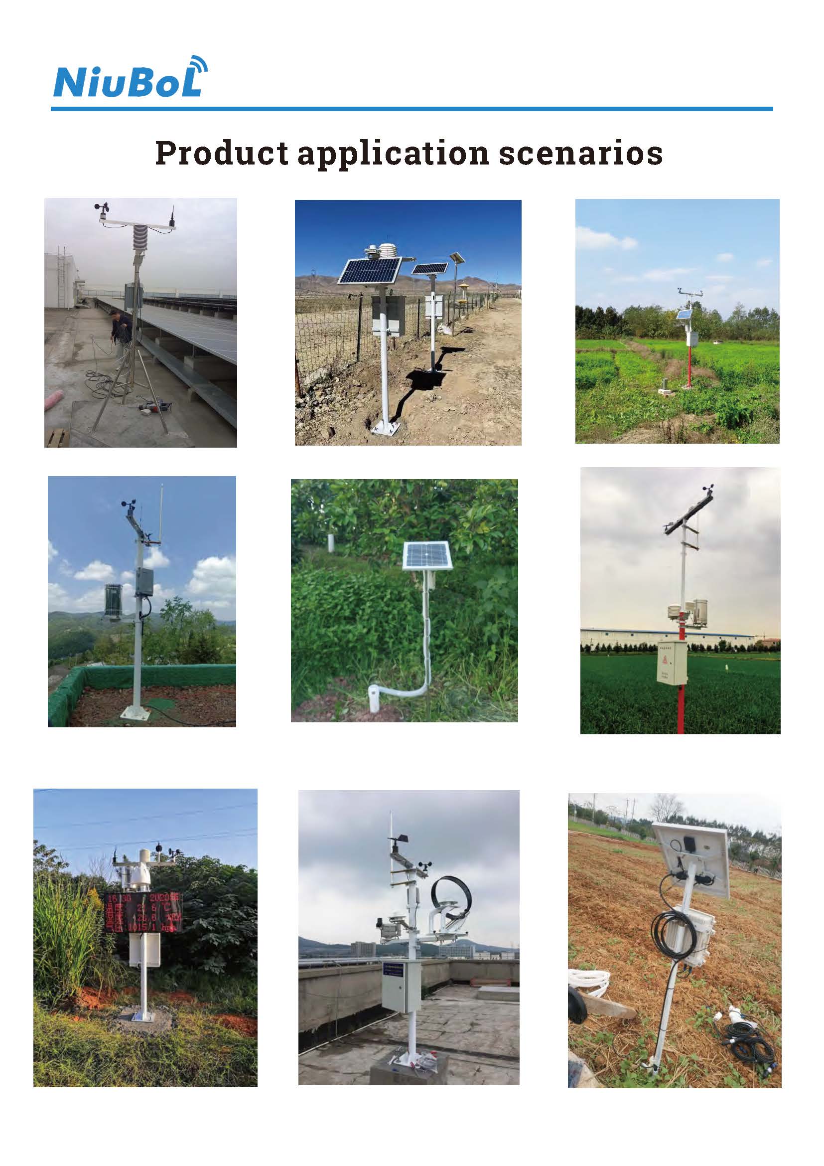
Select weather station parts according to their physical role. Shield air sensors while preserving ventilation, protect electronics in an appropriate cabinet and position instruments on a suitable support. Reviewing those relationships together prevents a well-packaged station from producing poorly exposed observations.
Prev:Wired vs Wireless Weather Station: Work Within Site Network Rules
Next:Weather Station Price Guide: Types, Costs & Buying Factors
Related recommendations
Sensors & Weather Stations Catalog
 Agriculture Sensors and Weather Stations Catalog-NiuBoL.pdf
Weather Stations Catalog-NiuBoL.pdf
Agriculture Sensors Catalog-NiuBoL.pdf
Water Quality Sensor Catalog-NiuBoL.pdf
Related products
 Combined air temperature and relative humidity sensor
 TDR Soil Moisture & Temperature Sensor for irrigation| RS485 |4-20mA| NBL-S-THR
 Soil pH sensor RS485 soil Testing instrument soil ph meter for agriculture |NBL-S-PH
 Wind Speed sensor Output Modbus/RS485/Analog/0-5V/4-20mA
 Tipping bucket rain gauge for weather monitoring auto rainfall sensor RS485/Outdoor/stainless steel
 Pyranometer Solar Radiation Sensor 4-20mA/RS485


Screenshot, WhatsApp to identify the QR code
WhatsApp number:+8615367865107
(Click on WhatsApp to copy and add friends)

