





— Blogs —
—Products—
 Consumer hotline +8618073152920
WhatsApp:+8615367865107
Address:Room 102, District D, Houhu Industrial Park, Yuelu District, Changsha City, Hunan Province, China
Product knowledge
Time:2026-08-03 09:36:50 Popularity:282
Quick Answer: Select an online conductivity sensor for each RO measurement point, not one broad range for the entire plant. Feed and permeate may need different spans. Compare values in the same units and on a compatible temperature basis, with representative sampling and valid timing. A conductivity ratio can support investigation, but it is not a complete membrane-performance assessment or proof of finished-water quality.
Conductivity is a practical online indicator of ionic changes in RO feedwater, rinse water and industrial loops. It cannot identify the ion responsible for a change. Where a specific contaminant or hardness must be assessed, retain the appropriate separate measurement.
Mark the feed point after the treatment and mixing stages that define the membrane feed. Mark permeate before or after any blending, remineralization or storage according to the actual task. A probe after blending does not measure membrane permeate alone.
Record which operating state each reading represents. Startup, flushing, recirculation and normal production can produce different observations. Do not compare a current feed value with yesterday's permeate result or treat a stagnant sample line as flowing product water.
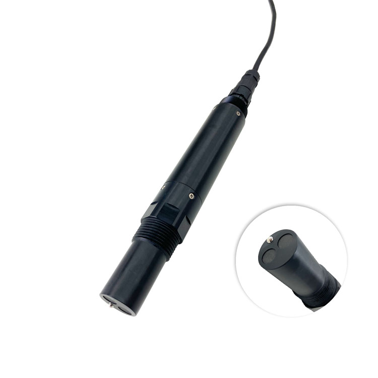
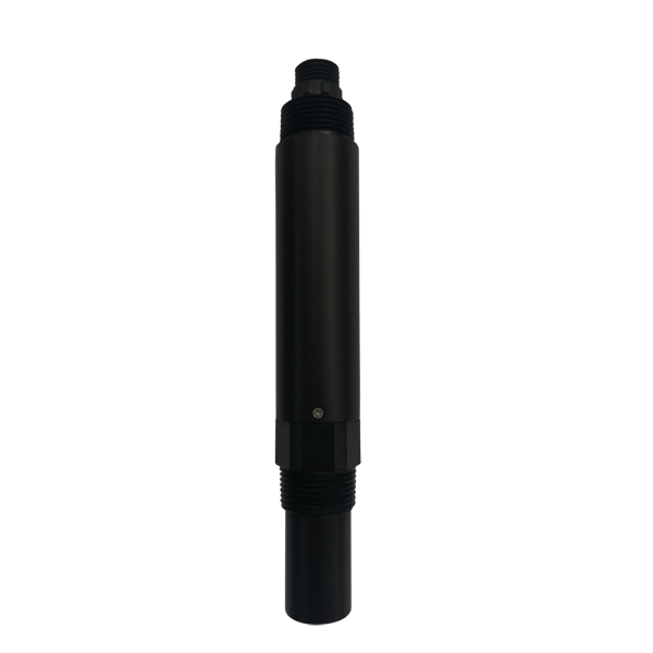
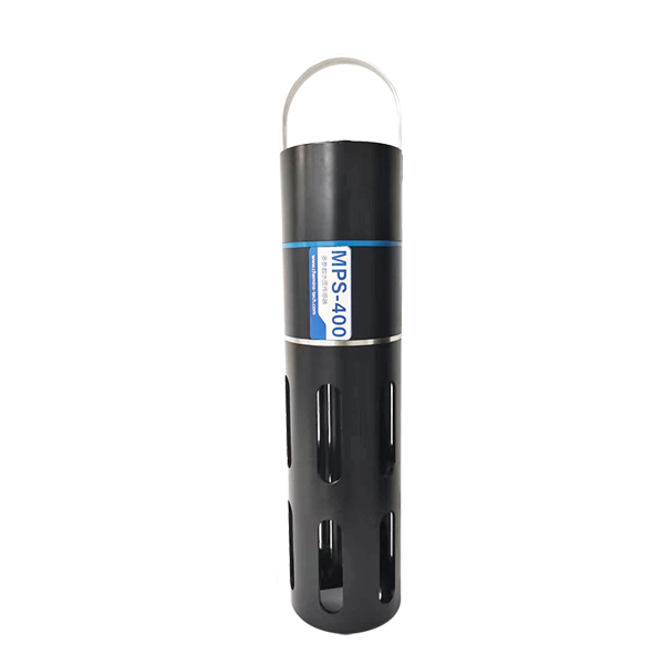
The opening image shows the configurable NiuBoL NBL-WQ-EC. The separate EC-4A below lists a 0-5000 uS/cm span. Their accuracy statements are not identical.
| Item | NBL-WQ-EC | EC-4A |
|---|---|---|
| Configured range | 0-20.00, 0-200.0 or 0-5000 uS/cm; or 0-200.0 mS/cm | 0-5000 uS/cm |
| Conductivity accuracy | +/-1% F.S. | +/-1.5% F.S. |
| Temperature accuracy; compensation | +/-0.3 degrees C; Pt1000 automatic compensation | +/-0.3 degrees C; Pt1000 automatic compensation |
| Working liquid conditions | 0-50 degrees C; pressure below 0.6 MPa | 0-50 degrees C; pressure below 0.6 MPa |
| Supply; consumption | 12-24 VDC +/-10%; 0.2 W at 12 V | 12-24 VDC; 0.2 W at 12 V |
| Signal | RS485 Modbus RTU | RS485 Modbus RTU; optional 4-20 mA |
| Construction; protection | ABS, SUS316L or PVC by configuration; IP68 | ABS/SUS316L configuration; IP68 |
| Mounting; cable | Immersion or 3/4 NPT; standard 5 m | Immersion or 3/4 NPT; standard 5 m shielded |
For the NBL-WQ-EC, 1% of a 20 uS/cm span is 0.2 uS/cm; 1% of a 5000 uS/cm span is 50 uS/cm. EC-4A's 1.5% term on 5000 uS/cm is 75 uS/cm. These are specification calculations, not measured field errors. A broad-range probe is not established as suitable for a 2 uS/cm permeate decision merely because it displays a number there.
Use the conductivity range and cell-selection guide for the underlying configuration choices. For the RO enquiry, provide normal feed and permeate values, decision levels and credible excursions separately.
Confirm whether the selected registers provide conductivity at sample temperature or a compensated value at a reference temperature. Record the actual compensation setting and method. Do not compare an uncompensated feed value with a temperature-compensated permeate value while describing the ratio as a water-quality change.
Automatic compensation at the sensor does not justify applying a second correction at the PLC. Keep the raw or compensated status clear at the probe, receiving controller and exported record. A common reference basis is necessary, but it does not remove every composition-dependent limitation of the compensation method.
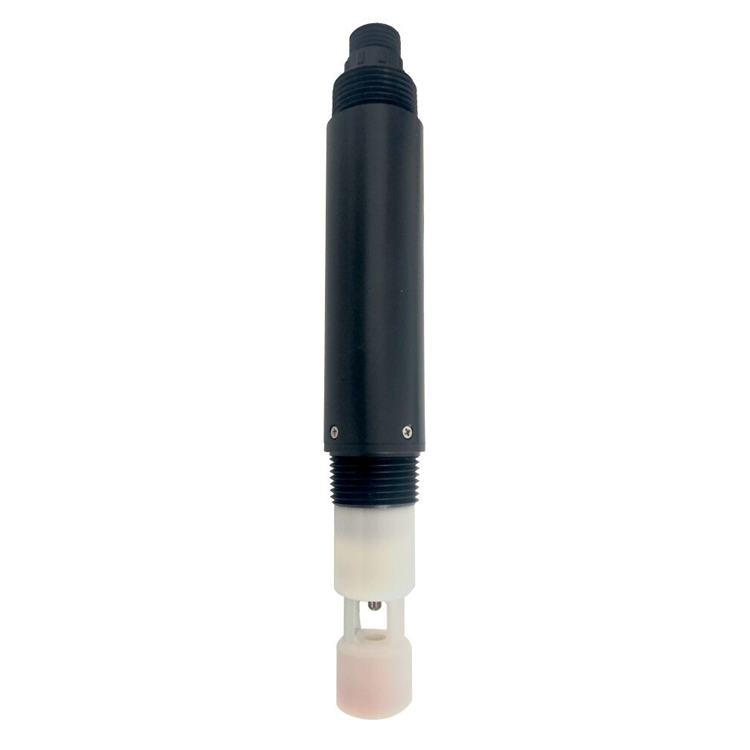
The dedicated salinity instrument below is a separate measurement configuration. A PSU value cannot be inserted directly into a conductivity ratio, and salinity conversion is not an ion analysis for low-conductivity permeate.
For a simple conductivity comparison, calculate the permeate-to-feed ratio only after converting both readings to the same units. With illustrative values of feed 0.500 mS/cm and permeate 2.00 uS/cm, the feed is 500 uS/cm. The ratio is 2/500 = 0.004, or 0.4%; its complement is a 99.6% conductivity reduction indicator.
This arithmetic is not a NiuBoL test result, a guaranteed salt rejection or a normalized RO performance calculation. Different ion mixtures, temperature treatment, operating pressure, recovery and flow conditions affect interpretation. Use the membrane supplier's applicable performance procedure for a membrane acceptance or cleaning decision.
| Observation | Check before blaming the membrane | Reason |
|---|---|---|
| Ratio changes after startup | Operating state, sample flushing and water delivery | The two observations may not represent comparable production |
| Only one channel changes with temperature | Compensation basis and actual sample temperature | A configuration mismatch can resemble an ionic change |
| Permeate increases after a pipework change | Blending, leakage paths and sample-point identity | The point may no longer represent unblended permeate |
| Small permeate changes dominate the conclusion | Low-range accuracy, reference check and sample contamination | The displayed increment is not the total uncertainty |
Use a representative, continuously renewed sample with the measuring region fully wetted and free of trapped bubbles. Check holders, fittings, seals and the ordered wetted materials against the water and cleaning exposure. Do not infer a complete holder's pressure approval from the probe's rating.
For low-conductivity water, keep comparison containers and sample handling clean and minimize unnecessary exposure before checking. A delayed open-container sample may not reproduce the inline condition. Record sampling method, temperature and time when investigating disagreement.
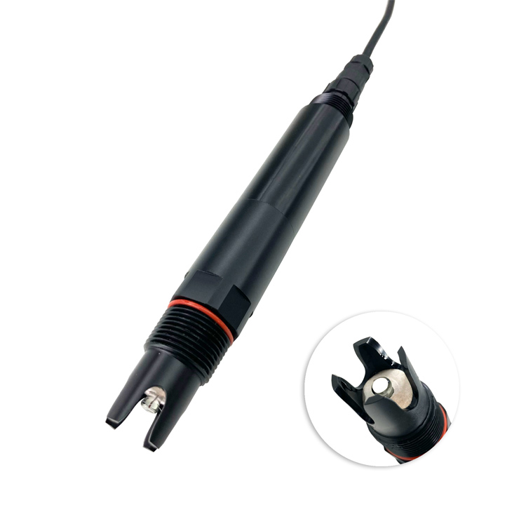
The separate pH probe below addresses another process measurement. It does not establish the conductivity span or correct an EC comparison. Add it where the treatment task requires pH, not merely to increase the station's channel count.
At the PLC, RTU or data logger, identify both point locations, model spans, RS485 Modbus RTU addresses, units and temperature basis. Convert mS/cm and uS/cm explicitly where required; 1 mS/cm equals 1000 uS/cm.
Verify each channel with an appropriate standard and installed comparison, then check the calculation with known test values. Ensure a missing or stale feed value does not become a valid denominator. Test the approved handling of flushing, maintenance and unavailable measurements before using the ratio in an operating decision.
For a NiuBoL quotation, send the two point schedules, expected values, required decision tolerance, receiver details and sample arrangement. A multiparameter assembly also needs its actual EC module and range specified; its family name does not demonstrate low-conductivity capability.
Only if its error and useful operating band suit both decisions. Check the absolute full-scale error at the permeate level; a separate lower-range configuration may be needed.
No. It is the complement of a conductivity ratio under the stated conditions. Establish the applicable concentration basis and membrane-performance method before assigning a salt-rejection claim.
Not if the selected sensor output has already been compensated on the intended basis. Verify the actual register and settings instead of applying an undocumented second correction.
Check sample identity, temperature, timing, handling and contamination. A later open-container measurement may describe changed water rather than a failed inline probe.
No. Conductivity reflects ionic behavior, not every contaminant or finished-water requirement. Retain the parameter-specific and reference checks required by the process.
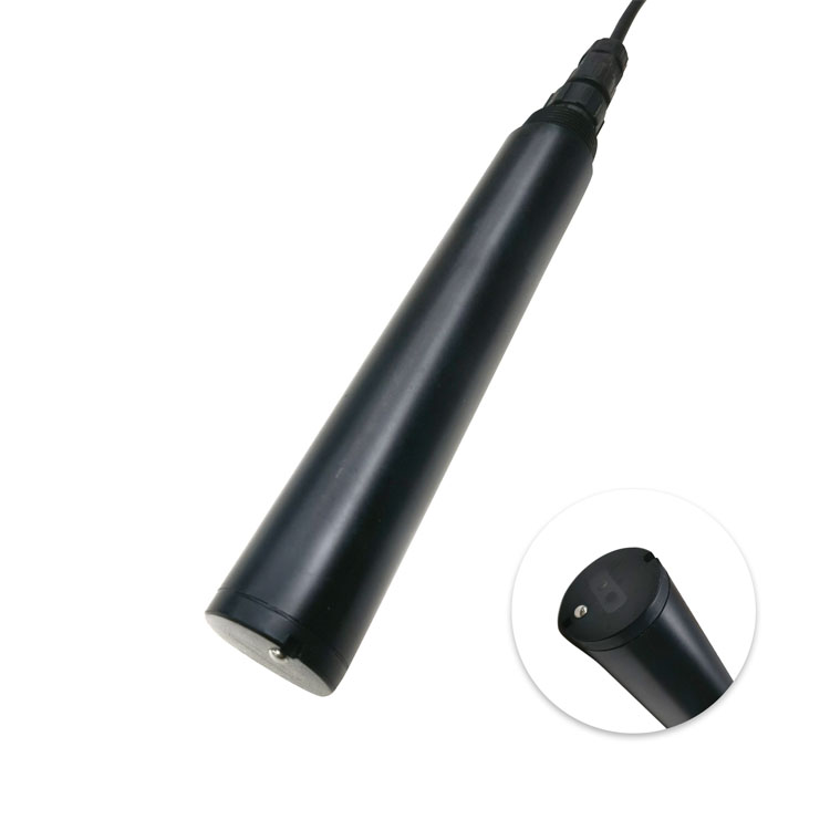
An online conductivity sensor supports RO investigation when each point has the right range, sample and comparison basis. Validate the two channels before using their ratio, and keep conductivity observations separate from complete membrane-performance and water-quality conclusions. A turbidity channel remains a separate particle-related measurement, not an EC verification.
Prev:Online ORP Sensor Replacement: Can You Reuse the Existing Setpoint?
Next:Residual Chlorine Sensor for Dosing: Restart After Sample-Flow Loss
Related recommendations
Sensors & Weather Stations Catalog
 Agriculture Sensors and Weather Stations Catalog-NiuBoL.pdf
Weather Stations Catalog-NiuBoL.pdf
Agriculture Sensors Catalog-NiuBoL.pdf
Water Quality Sensor Catalog-NiuBoL.pdf
Related products
 Combined air temperature and relative humidity sensor
 TDR Soil Moisture & Temperature Sensor for irrigation| RS485 |4-20mA| NBL-S-THR
 Soil pH sensor RS485 soil Testing instrument soil ph meter for agriculture |NBL-S-PH
 Wind Speed sensor Output Modbus/RS485/Analog/0-5V/4-20mA
 Tipping bucket rain gauge for weather monitoring auto rainfall sensor RS485/Outdoor/stainless steel
 Pyranometer Solar Radiation Sensor 4-20mA/RS485


Screenshot, WhatsApp to identify the QR code
WhatsApp number:+8615367865107
(Click on WhatsApp to copy and add friends)

