

— Blogs —
—Products—
 Consumer hotline +8618073152920
 WhatsApp:+8615367865107
Address:Room 102, District D, Houhu Industrial Park, Yuelu District, Changsha City, Hunan Province, China
Product knowledge
Time:2026-08-24 09:06:00 Popularity:199
Selection of TDS Meter Module V1 should begin with the measurement duty, site condition and receiving-system interface. The sampling point is often the hidden reason for poor water quality data. A good online sensor package still fails when installed in dead water, heavy sediment, air bubbles or a point that operators cannot maintain.
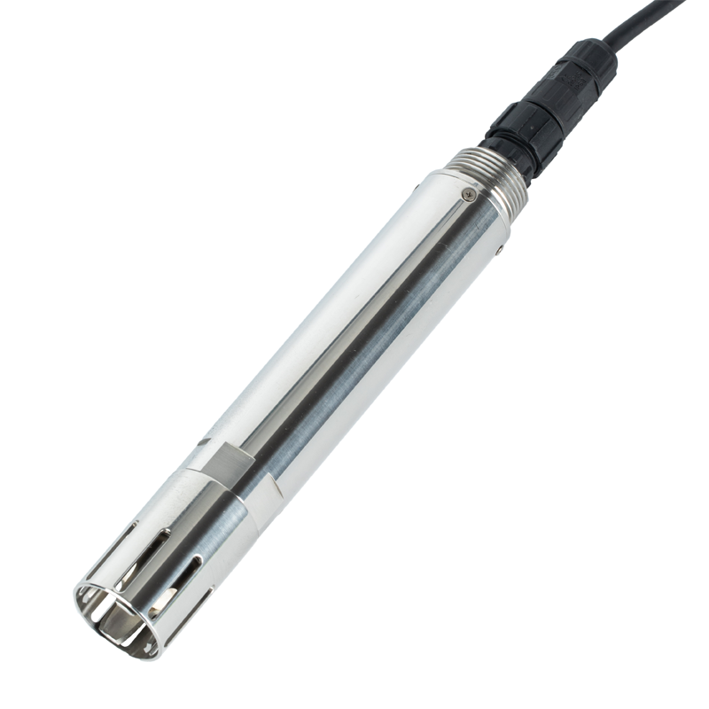
For NiuBoL buyers and system integrators, the practical question is whether TDS Meter Module V1 can be specified, installed, connected and accepted without creating hidden work after delivery.
| Item | Project Specification | Why It Matters |
|---|---|---|
| Parameter options for TDS Meter Module V1 | pH, ORP, EC, TDS, salinity, turbidity, DO, COD, ammonia, temperature | Select only parameters that change a real operating decision. |
| Communication for TDS Meter Module V1 | RS485 / Modbus RTU for industrial sensors | Supports PLC, RTU, logger and gateway projects. |
| Power supply for TDS Meter Module V1 | 12-24 V DC according to sensor and controller | Fits field cabinets and solar-powered nodes. |
| Output scope for TDS Meter Module V1 | Single sensor, multi-parameter controller or cloud gateway | Defines whether the buyer needs device data or a complete station. |
| Protection for TDS Meter Module V1 | Waterproof probe and outdoor enclosure when required | Matches wet, dusty and remote environments. |
| Service item for TDS Meter Module V1 | Cleaning, calibration check, cable inspection and data audit | Controls long-term data quality. |
The engineering review considers TDS Meter Module V1 as a project component, so the decision includes measurement purpose, site condition, installation, data interface, acceptance and later service.
The required class of TDS Meter Module V1 depends on whether the project needs continuous data, remote alarms or documented handover records. The suitable sampling point is reachable, representative and serviceable. If one of those three conditions is missing, the project should fix the layout before buying more sensors.
Installation quality is part of measurement quality for TDS Meter Module V1, so exposure and service access must be checked together. For pipes, check pressure, flow and bubble risk. For ponds and tanks, check depth, sediment, sunlight and access for safe cleaning.
For TDS Meter Module V1, parameter count should follow sample point. For TDS Meter Module V1, prioritize measurements that support a defined operating decision and reserve expansion channels only for documented future use.
For TDS Meter Module V1, RS485 Modbus RTU is useful when sample point data must enter a controller or gateway without manual entry. Ask for the register map before panel wiring.
For NiuBoL matching of TDS Meter Module V1, provide measured medium, expected range, installation drawing, cable length, power supply and sample point requirement.
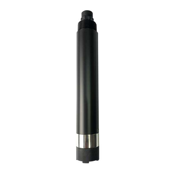
| Item | Project Specification | Why It Matters |
|---|---|---|
| Prototype board for TDS Meter Module V1 | Low cost and flexible testing | Good for learning, not unattended procurement |
| Portable meter for TDS Meter Module V1 | Manual checks and spot verification | Useful for inspection rounds |
| Industrial online sensor for TDS Meter Module V1 | Waterproof cabling, stable output and integration | Required for alarms and remote data |
For TDS Meter Module V1, RS485 Modbus RTU should be specified with device address, baud rate, register map and wiring note. This is especially important when the project depends on sampling location and the data must enter a PLC, RTU, logger or gateway without manual transcription.
If TDS Meter Module V1 is supplied as a station rather than a single device, confirm whether 4G, WiFi, LoRa, Ethernet, local display or cloud upload is included. For TDS Meter Module V1, the project document should identify communication charges, verified coverage, data retention and the party responsible for platform access.
TDS Meter Module V1 sits between the field condition and the control or reporting platform. Depending on the selected TDS Meter Module V1 package, document the exact signal path to the controller, PLC, RTU, logger, gateway or platform rather than assuming every destination is included. The TDS Meter Module V1 quotation should distinguish supplied equipment and documentation from cabling, mounting, panel work and commissioning assigned to the installer.
For TDS Meter Module V1, the project boundary should be written as a scope list: measuring hardware, cable, mounting parts, power supply, enclosure, controller or gateway, data destination and service responsibility. The sampling location angle decides which of those items must be included in the first quotation.
Field challenge: TDS Meter Module V1 must produce usable evidence under the sample point condition, where access, timing, fouling, exposure or reporting duty can change the result.
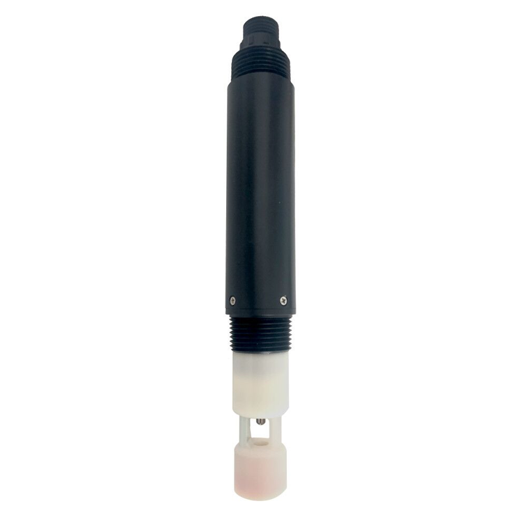
Integration plan: For TDS Meter Module V1, choose mounting, power, communication and service access around the sample point objective, then record those choices for quotation and handover.
User value: For TDS Meter Module V1, stable records help the site compare normal operation with abnormal events and support later quotation or maintenance review.
User value: For TDS Meter Module V1, the buyer receives earlier evidence for field action instead of waiting for scattered manual notes.
User value: For TDS Meter Module V1, acceptance becomes easier because installation, data and service conditions are recorded before handover.
User value: For TDS Meter Module V1, operators can compare locations, time periods and service actions with less argument about where the data came from.
For TDS Meter Module V1, the RFQ should be written around the project result rather than a short product name. Include these points so suppliers quote the same scope:
The main risk for TDS Meter Module V1 projects is buying a device without defining the field condition. Before production or shipment of TDS Meter Module V1, confirm range, cable route, mounting arrangement, cleaning access, power and the receiving data interface.
For TDS Meter Module V1, quality should be judged against a written baseline for sample point. The TDS Meter Module V1 handover file should record installation conditions and the first operating result so later troubleshooting begins from a verified baseline.
TDS Meter Module V1 fits projects where sample point changes a field decision, a maintenance visit or a handover record. The practical purpose of TDS Meter Module V1 is to produce repeatable field evidence for selection, operation and acceptance, not merely to match a device name.
TDS Meter Module V1 is not suitable when the site has no service access, no power plan, no data user or only occasional manual checking. Where continuous TDS Meter Module V1 monitoring is not yet justified, a defined survey or pilot package can establish the site range and workflow before permanent deployment.
For TDS Meter Module V1, the parameter list should be tied to sample point. The site review for TDS Meter Module V1 should keep the first package focused on measurements that change operation, then add expansion channels only when the site has a real plan to use them.
For TDS Meter Module V1, this point should be written into the quotation or acceptance sheet because it affects installation labor, data trust and later troubleshooting. Before TDS Meter Module V1 ships, assign responsibility for installation, configuration, data access and routine service among the contractor, distributor and site operator.
For TDS Meter Module V1, reserve power capacity, cabinet space, communication addresses and mounting locations only when the project expects expansion. Any unconfirmed TDS Meter Module V1 item should remain outside the initial quotation.
A clear quotation for TDS Meter Module V1 should separate the measuring device, cable, bracket, controller, gateway, power supply, enclosure and spare parts. Within the TDS Meter Module V1 supply scope, this makes price comparison fair and prevents a low initial quote from becoming incomplete during installation.

A1: Select TDS Meter Module V1 parameters from the decisions the monitoring point must support, then confirm expected ranges, response timing and reporting duties. Any TDS Meter Module V1 parameter without a defined user, alarm or operating action should remain outside the initial package.
A2: Use online TDS Meter Module V1 monitoring when the project needs continuous trends, remote alarms, control input or traceable records between site visits. Use manual TDS Meter Module V1 testing when occasional inspection is sufficient and no immediate action depends on the interval between samples.
A3: The TDS Meter Module V1 sampling point determines whether the reading represents the intended water condition and whether the equipment can be serviced safely. Review TDS Meter Module V1 flow, depth, mixing, sediment, bubbles, contamination sources, cable routing and access before fixing the installation drawing.
A4: Verify the TDS Meter Module V1 interface end to end: wiring, device address, baud rate, parity, register address, data type, scaling and engineering unit. During TDS Meter Module V1 acceptance, compare the local value with the PLC, RTU or logger value and retain the tested register map.
A5: Specify a complete TDS Meter Module V1 station when the scope must include field measurement, power, mounting, data acquisition, communications, storage, alarms and remote access as one deliverable. A sensor-only TDS Meter Module V1 scope is appropriate when the existing controller and infrastructure are already documented and compatible.
A6: Weak TDS Meter Module V1 data commonly results from an unrepresentative point, poor mounting, fouling, bubbles, damaged cabling, incorrect scaling, unstable power or mismatched timestamps. Troubleshooting TDS Meter Module V1 data should begin with the as-found installation and signal path before changing calibration values.
A7: The TDS Meter Module V1 RFQ should state the medium, expected range, measuring-point drawing, mounting method, cable distance, available power, output interface, destination system, quantity, schedule and acceptance method. It should also assign TDS Meter Module V1 installation, configuration and routine service responsibilities.
A8: The TDS Meter Module V1 handover should verify the physical installation, local and host readings, engineering units, timestamps, alarms, communications and recovery after a controlled restart. Retain the accepted TDS Meter Module V1 configuration, register map, photographs and initial comparison record.
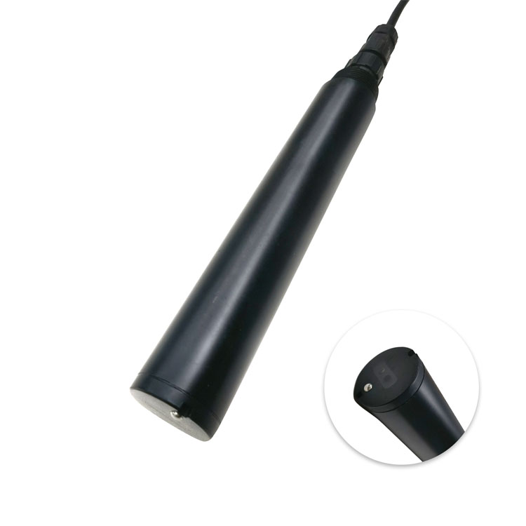
TDS Meter Module V1 Projects should be treated as a specification and project risk question, not a simple product label. A workable TDS Meter Module V1 purchase specification connects the site problem with the required range, installation, interface, maintenance owner and acceptance evidence.
The quotation for TDS Meter Module V1 should distinguish the field device, accessories, controller interface and site-service scope. For model matching, send NiuBoL the sample point objective, site medium, mounting condition, output requirement, cable length, quantity and schedule. With those TDS Meter Module V1 inputs, the supplier can itemize the field device, accessories, communication components and service responsibilities on a comparable basis.
Prev:Online TSS Meter: Industrial Selection Guide for Online Monitoring Projects
Next:ORP Oxidation Reduction Potential Meter: Online Water Quality Monitoring Selection Guide
Related recommendations
Sensors & Weather Stations Catalog
 Agriculture Sensors and Weather Stations Catalog-NiuBoL.pdf
Weather Stations Catalog-NiuBoL.pdf
Agriculture Sensors Catalog-NiuBoL.pdf
Water Quality Sensor Catalog-NiuBoL.pdf
Related products
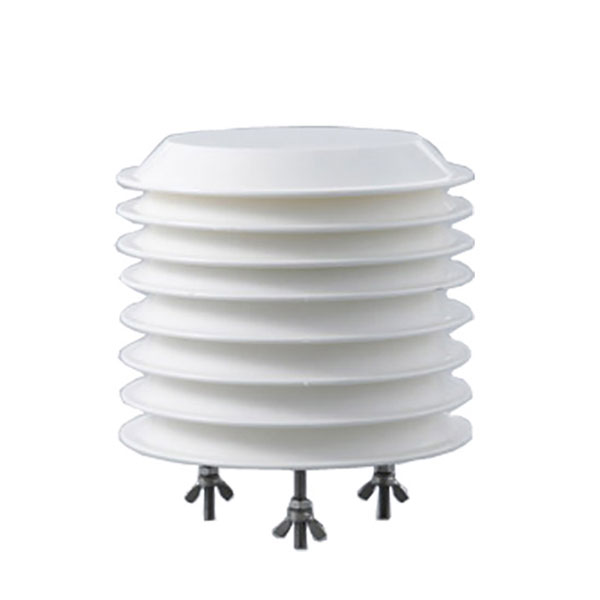 Combined air temperature and relative humidity sensor
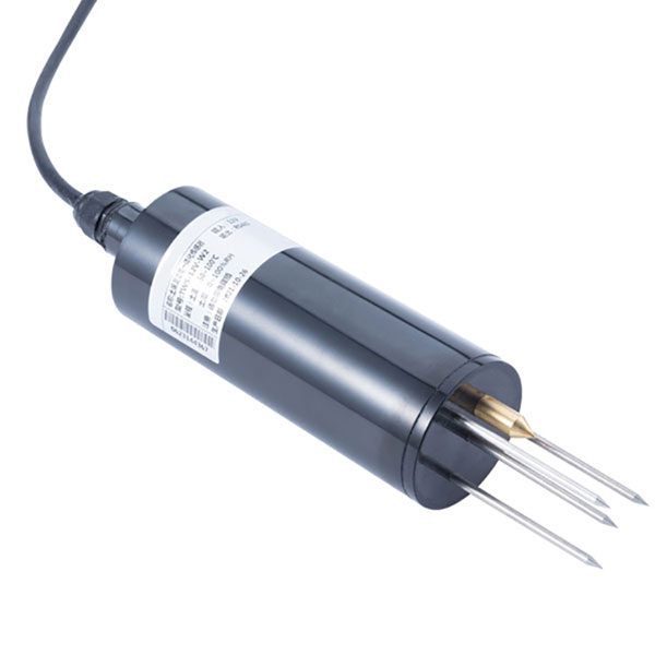 TDR Soil Moisture & Temperature Sensor for irrigation| RS485 |4-20mA| NBL-S-THR
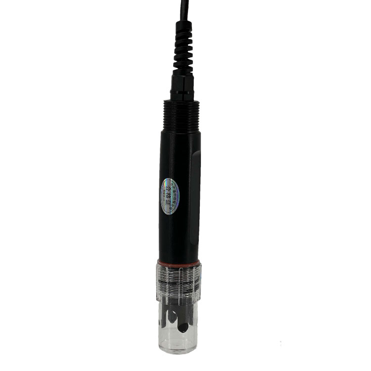 Soil pH sensor RS485 soil Testing instrument soil ph meter for agriculture |NBL-S-PH
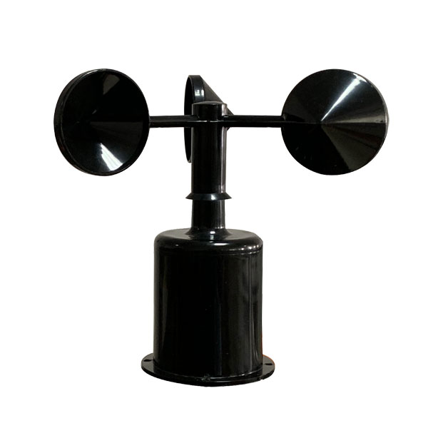 Wind Speed sensor Output Modbus/RS485/Analog/0-5V/4-20mA
 Tipping bucket rain gauge for weather monitoring auto rainfall sensor RS485/Outdoor/stainless steel
 Pyranometer Solar Radiation Sensor 4-20mA/RS485

Screenshot, WhatsApp to identify the QR code
WhatsApp number:+8615367865107
(Click on WhatsApp to copy and add friends)