





— Blogs —
—Products—
 Consumer hotline +8618073152920
WhatsApp:+8615367865107
Address:Room 102, District D, Houhu Industrial Park, Yuelu District, Changsha City, Hunan Province, China
Product knowledge
Time:2026-08-18 09:06:00 Popularity:276
Quick Answer: A TDS sensor with Arduino can use an industrial RS485 conductivity probe, but it is not an analogue probe wired directly to an input pin. The system needs a suitable sensor power supply, an RS485 transceiver or supported interface, Modbus RTU decoding and a defined conductivity-to-TDS conversion. Prove the local measurement first; cloud upload is a separate stage.
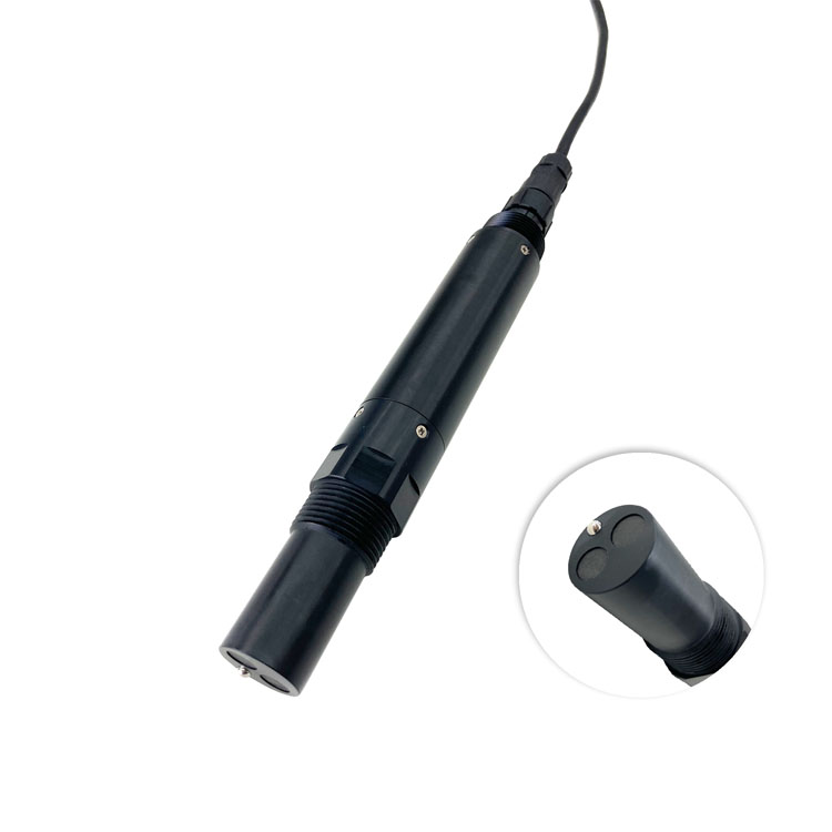
The phrase TDS sensor with Arduino covers two different arrangements: an analogue conditioning board read by an ADC, or a digital industrial probe read over a serial bus. Their wiring and software are not interchangeable. For the NiuBoL NBL-WQ-EC conductivity sensor, use the RS485 Modbus RTU path. Connecting its A and B conductors to ordinary receive and transmit pins does not provide the required electrical interface.
An Arduino-based controller can be useful when the project team owns firmware development and needs a customised acquisition routine. A configured industrial data logger is often more appropriate when the deliverable is an unattended field installation with defined support responsibilities. The choice is about who will maintain the complete measurement path, not a claim that either platform automatically produces more accurate water chemistry.
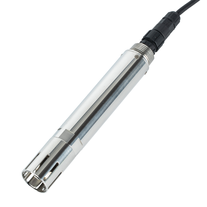
The pH sensor pictured above is a separate acidity channel. It is not the conductivity probe used in the TDS example below. Likewise, the dissolved oxygen sensor can add oxygen information to a water-monitoring project, but its readings cannot be used as TDS. Preserve distinct channel names and units from the beginning of a multiparameter design.
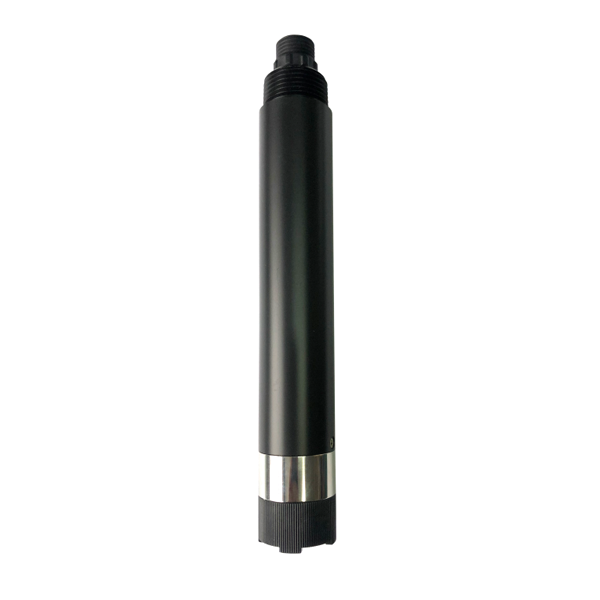
The NBL-WQ-EC requires 12-24 V DC, with a stated consumption of 0.2 W at 12 V. A controller's 3.3 V or 5 V logic supply is a different requirement. Do not power the probe from a logic pin, and do not apply the sensor's field supply to a microcontroller input. Use a suitable regulated supply arrangement and verify the voltage at the probe with the complete system operating.
| Connection layer | Required provision | Error to avoid |
|---|---|---|
| Probe supply | 12-24 V DC matched to NBL-WQ-EC | Assuming a board's low-voltage output can power the field sensor |
| Controller logic | Interface compatible with the selected board's logic voltage | Using an incompatible receiver output on a lower-voltage input |
| Serial electrical interface | RS485 transceiver or an appropriately supported integrated RS485 port | Connecting A/B directly to UART TX/RX |
| Protocol | Modbus RTU client that matches the probe's configuration | Assuming RS485 alone specifies register format or units |
| External connection protection | Terminations, reference/isolated interface and transient protection selected for the installation | Treating a bench jumper-wire test as proof of outdoor robustness |
For the four-wire NBL-WQ-EC configuration, red is supply positive, black is GND, blue is 485A and white is 485B. Confirm the delivered cable definition before connection. RS485 terminal naming differs between interface products, so establish polarity from their electrical definitions rather than wire colour alone. A separately screened or differently terminated cable may need additional documentation.
Use a linear bus with short branches where several probes share the cable. Choose termination for the cable and network; do not enable an extra terminator at every sensor. Ground-potential differences and exposed outdoor wiring require a deliberate reference, isolation and surge-protection design. A shield is not a substitute for resolving an unsuitable common-mode voltage or an unsafe bonding arrangement.
The NBL-WQ-EC online conductivity sensor is offered in different conductivity ranges. Select the range and cell configuration for the expected water, then verify whether the delivered version provides the required TDS output. A single part-family name does not establish every range, material and register option.
| Selected NBL-WQ-EC item | Available specification | Integration decision |
|---|---|---|
| Conductivity ranges | 0-20 microS/cm; 0-200 microS/cm; 0-5000 microS/cm; 0-200 mS/cm | Order one appropriate range; do not assume automatic switching between all four |
| Digital output | RS485 / Modbus RTU | Use the register map applicable to the supplied range and firmware |
| Supply and stated consumption | 12-24 V DC; 0.2 W at 12 V | Budget the controller, storage and modem separately |
| Protection | IP68 probe | Protect the controller and field cable terminations independently |
| Mounting and standard cable | 3/4 NPT; 5 m cable | Check clearances, retrieval access and cable-extension requirements |
| Wetted materials | ABS, SUS316L or PVC depending on configuration | Select the actual construction for water chemistry and cleaning exposure |
TDS is an estimate derived from conductivity, not a direct separation and weighing of all dissolved material. In a simplified conversion, TDS in mg/L equals conductivity in microS/cm multiplied by a suitable coefficient. The coefficient depends on the water and reporting convention. Changing it changes the TDS result without changing the underlying conductivity measurement.
For the NBL-WQ-EC six-register measurement layout, the stated serial default is 9600 baud, 8 data bits, no parity and 1 stop bit. Function 03 reads six 16-bit registers beginning at protocol address 0x0000. They contain three value-and-decimal-place pairs: conductivity, temperature and TDS. This is not an instruction to interpret the twelve response bytes as three floating-point numbers.
The human-readable label 40001 and the protocol offset 0x0000 refer to different address conventions for this layout. Check which convention the chosen Modbus library expects. Confirm the delivered device address as well: the documented default is 1 for the common ranges, with 2 stated for the 200 mS/cm variant. Do not connect several default-address probes to the same bus before assigning distinct addresses.
| Illustrative returned pair | Decoded result | Condition |
|---|---|---|
| Conductivity 1000, decimal places 0 | 1000 microS/cm | Example assumes a compatible microS/cm range and register layout |
| Temperature 253, decimal places 1 | 25.3 degrees C | Decode the temperature pair separately |
| TDS 640, decimal places 0 | 640 mg/L | Illustrates a coefficient of 0.64 applied to 1000 microS/cm |
These numbers illustrate decoding, not a factory test result. The documented coefficient default is 0.64, but the correct coefficient for a project must suit its water. Establish temperature-compensation and reference-temperature conventions when comparing instruments. Never multiply a value in mS/cm as though it were microS/cm: 1 mS/cm equals 1000 microS/cm.
Start with read-only transactions. Reject incomplete frames, CRC failures and Modbus exception responses. Store the raw returned values during commissioning so a later unit or decimal error can be reconstructed. Keep calibration and coefficient writes out of the routine polling loop; an accidentally repeated write can change the measurement rather than simply read it.
After local readings are correct, add logging and the selected network connection. Store the acquisition time separately from the upload time. Include the probe identity, conductivity unit, TDS coefficient, temperature convention and validity state in the data design. A retained last value after a timeout must be labelled as stale, not presented as a fresh successful measurement.
If local buffering is required, test a disconnected-network period and examine the exported records after reconnection. Check for missing intervals, duplicate timestamps and the wrong time zone. Neither an SD card nor a cloud dashboard automatically guarantees replay or ordered recovery. Verify those behaviours in the actual firmware and service configuration rather than assuming they follow from the hardware list.
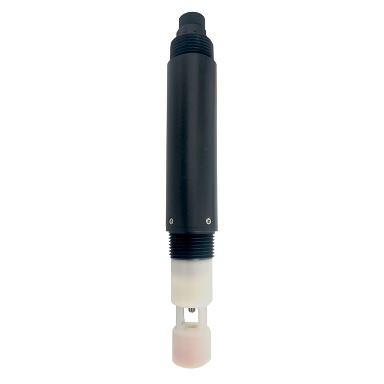
Additional BOD-related or turbidity probes, pictured in this article, need independent polling definitions and validation. They also add power demand and service work. They should be included because the water-monitoring task needs their respective organic-response or particle observations, not because a cloud page has unused spaces for more numbers.

An Arduino prototype is a reasonable route for controlled trials, custom research and projects with an identified firmware maintainer. Before leaving it unattended, test power interruption, failed reads, storage limits and clock recovery. Enclose it appropriately and inspect its power and interface protection. A successful afternoon test on a desk does not establish a seasonal field operating record.
For a contractor handing over a remote installation, compare that development effort with a configured NiuBoL gateway or data acquisition arrangement. Check the exact supported register mapping, storage behaviour, communications and export format. The gateway still needs commissioning with the selected EC probe; buying industrial hardware does not eliminate unit errors or an unsuitable TDS coefficient.
A useful price comparison separates the probe and interface hardware from firmware development, enclosure work, telemetry charges and ongoing support. Send NiuBoL the required range, board or logger interface, cable route and data destination. Ask for the applicable register definition and range-specific material options. Avoid selecting by a universal online TDS kit price that excludes the parts required for the installation.
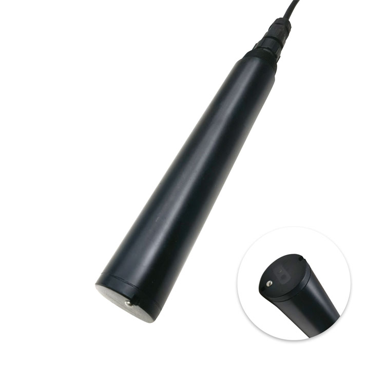
No. The RS485 version needs an electrically compatible RS485 interface and a Modbus RTU client. It is not an analogue-voltage TDS module. Supply the probe independently at its required field voltage and keep that voltage away from logic inputs.
Do not assume so. Devices can differ in register count, integer or floating-point format, decimal handling, units and supported functions. Reuse a tested communication library, but configure and verify each sensor's measurement definition separately.
Compare conductivity units, compensation conventions and the TDS coefficients first. Two instruments can report the same conductivity but different TDS estimates because their conversion factors differ. Do not recalibrate the EC channel solely to force agreement between unlike TDS conventions.
Flag the record as invalid or stale, retain the last successful acquisition time and log the communication error. Do not replace a missing result with zero TDS. Test recovery after the sensor and controller restart, including any alarm based on data age.
The probe provides its field measurement interface. A controller or gateway, network connection and configured destination are separate system elements. Include them in the quotation when remote access is required, and confirm data ownership, export and ongoing connection costs.
A TDS sensor with Arduino is workable when power, RS485 hardware, decoding and data validity are engineered together. For NBL-WQ-EC, establish the ordered conductivity range and register layout before coding, and preserve conductivity alongside the TDS estimate. Choose a supported data logger when a configured field system better matches the project's maintenance and delivery responsibilities.
Prev:TSS Measurement Instrument: Match Range, Particles and Sample Checks
Next:Dissolved Oxygen and pH Meter: Keep Aeration and Dosing Decisions Separate
Related recommendations
Sensors & Weather Stations Catalog
 Agriculture Sensors and Weather Stations Catalog-NiuBoL.pdf
Weather Stations Catalog-NiuBoL.pdf
Agriculture Sensors Catalog-NiuBoL.pdf
Water Quality Sensor Catalog-NiuBoL.pdf
Related products
 Combined air temperature and relative humidity sensor
 TDR Soil Moisture & Temperature Sensor for irrigation| RS485 |4-20mA| NBL-S-THR
 Soil pH sensor RS485 soil Testing instrument soil ph meter for agriculture |NBL-S-PH
 Wind Speed sensor Output Modbus/RS485/Analog/0-5V/4-20mA
 Tipping bucket rain gauge for weather monitoring auto rainfall sensor RS485/Outdoor/stainless steel
 Pyranometer Solar Radiation Sensor 4-20mA/RS485


Screenshot, WhatsApp to identify the QR code
WhatsApp number:+8615367865107
(Click on WhatsApp to copy and add friends)

