





— Blogs —
—Products—
 Consumer hotline +8618073152920
WhatsApp:+8615367865107
Address:Room 102, District D, Houhu Industrial Park, Yuelu District, Changsha City, Hunan Province, China
Product knowledge
Time:2026-08-03 09:36:59 Popularity:301
Quick Answer: A turbidity sensor for filter backwash must be selected for a defined water stream and decision. Filtered-water quality, dirty backwash water and post-wash recovery are different duties. Use a suitable range and sampling arrangement for each, and combine turbidity with the filter's approved headloss, runtime and valve-state logic. One turbidity value should not automatically authorize every backwash or return-to-service action.
Turbidity can add useful evidence to a timer-based filter routine, but only when the measurement represents the intended stream. An individual filter outlet can reveal that filter's behavior. A common header observes mixed water and does not identify which filter caused a change.
| Decision | Relevant stream | What the reading cannot establish alone |
|---|---|---|
| Investigate deterioration during a run | Representative filtered-water outlet | The cause of a rise or the correct backwash sequence |
| Observe solids leaving during washing | Backwash discharge | That finished-water quality has recovered |
| Review recovery after washing | The filter outlet during the approved recovery stage | Permission to bypass the plant's return-to-service criteria |
Mark these streams and valve states on the process diagram. If one instrument is switched between sample lines, identify flushing, transport and validity conditions for every change. Do not present mixed or transitional samples as a continuous record from one fixed point.
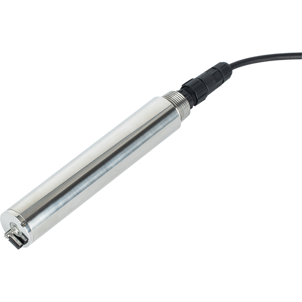
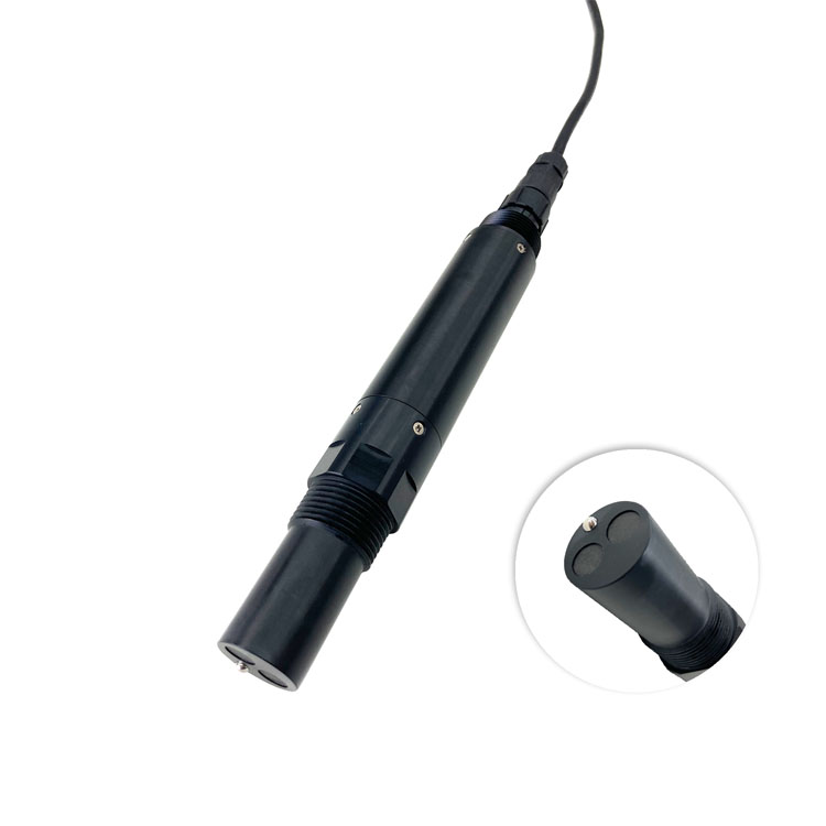
The opening image shows the NiuBoL TS-408-S immersion probe. Its 0-100, 0-1000 and 0-4000 NTU options are not interchangeable with the TSA-4 flow-through instrument shown below.
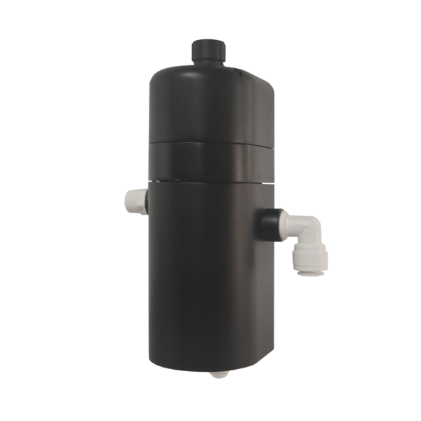
| TSA-4 item | Specification | Selection consequence |
|---|---|---|
| Range; resolution | 0-10.000 NTU; 0.001 NTU | Check the actual filtered-water band and excursions |
| Accuracy | +/-5% or +/-0.02 NTU, whichever is greater; confirm percentage basis | Do not assign the displayed increment as the acceptance tolerance |
| Detection; response | Listed detection limit 0.1 NTU; T90 below 90 s | Resolve suitability for low decision levels and short events |
| Water and flow conditions | 0-50 degrees C; pressure at most 0.2 MPa; recommended inlet flow at most 300 mL/min | Provide stable sample delivery and an unobstructed outlet |
| Supply; consumption | 12-24 VDC; 0.2 W at 12 V | Include panel and sample equipment separately |
| Output | RS485 Modbus RTU and 4-20 mA | Verify delivered wiring, units and receiver conversion |
| Construction; protection | Composite housing; wall-mounted flow-through assembly; IP65 | Not a submersible IP68 probe |
| Cable | Standard 5 m, customizable | Specify jacket, route and protected joints |
The 0.001 NTU resolution does not demonstrate reliable detection at that level. If the required decision is below or close to the listed detection limit, obtain demonstrated performance and an agreed comparison method before approving the instrument.
For the TS-408-S, confirm accuracy and the permitted operating envelope for the ordered span; do not borrow TSA-4 limits. Its installation guidance calls for at least 5 cm side clearance and 10 cm bottom clearance. These geometric requirements matter when fitting a bracket or narrow chamber.
Backwash and valve operations can introduce bubbles, pressure changes and temporary loss of representative sample. Check actual flow, line renewal and the optical region before interpreting a spike as particle breakthrough. Excessive smoothing may hide a short event; no smoothing may expose every hydraulic disturbance. Select and test the treatment of data for the actual control task.
Keep the measurement visible with its status. During an invalid sample interval, a held value must not silently become fresh evidence of good filtered water. Record the filter identity, valve stage, sample availability and observation time alongside turbidity.
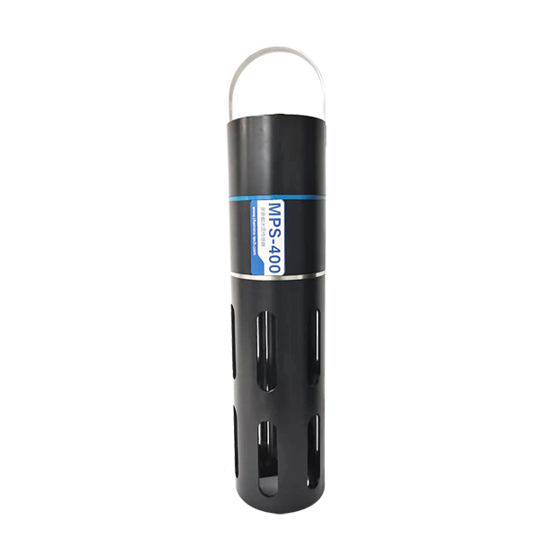
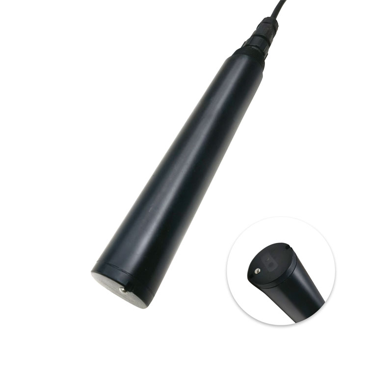
A multiparameter assembly, shown below, needs its selected turbidity module and range confirmed. The pH or conductivity channels in the same package do not validate low-turbidity performance.
Review the historical relationship between turbidity, filter loading, headloss and run duration under the site's actual conditions. A rising outlet value can justify investigation, but blindly initiating a wash from any high value can react to a dirty sample line or a bubble event.
Define who authorizes automatic backwash and which other conditions must be satisfied. Keep limits, delays and reset behavior specific to the process design. This article does not prescribe a universal NTU trigger, wash duration or finished-water criterion.
After washing, observe recovery at the correct outlet while following the plant's approved sequence. A clear-looking backwash discharge does not establish that the filter outlet is ready to return to service. Conversely, a valid high outlet result should not be erased from the record merely because the wash timer has ended.
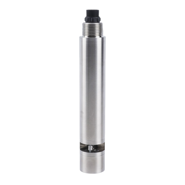
The separate COD probe below reports a different water property. It is not a turbidity reference or evidence that a filter has recovered. Claims of water savings need measured before-and-after operating records, not merely a sensor connection.
Send NiuBoL the filter diagram, target sample stream, normal and peak turbidity, required decision level, flow and pressure, and existing wash sequence. Add mounting access, receiver details and available reference observations.
Separate the price of the instrument from sampling fittings, flow control, wiring and any control-program change. The conductivity probe below may serve another treatment decision, but it should not be counted as a substitute for the required turbidity channel.
Only if its verified performance covers both decisions and the sampling arrangement remains valid. A large maximum range does not establish useful low-level performance.
No. The header observes mixed water. Identify individual filter behavior through an appropriate point arrangement and operating records.
No. TSA-4 is an IP65 wall-mounted flow-through assembly. Use its specified sample arrangement and keep its enclosure out of immersion.
No. Distinguish a valid process change from bubbles, sample interruption and maintenance. The approved filter-control strategy determines the response.
Comparable operating records showing wash frequency, duration, water use and relevant treated-water performance. Installing a turbidity sensor alone does not establish the result.
A turbidity sensor for filter backwash is useful when the stream, range and operating decision are defined. Keep filtered-water quality, wash discharge and recovery separate, verify low-level capability and test the whole sequence. Use measured operating evidence to evaluate any claimed optimization.
Prev:Ammonia Nitrogen Sensor Across a Biofilter: What the Difference Means
Next:Multi-Parameter Water Quality Probe for Stormwater: Capture the Complete Event
Related recommendations
Sensors & Weather Stations Catalog
 Agriculture Sensors and Weather Stations Catalog-NiuBoL.pdf
Weather Stations Catalog-NiuBoL.pdf
Agriculture Sensors Catalog-NiuBoL.pdf
Water Quality Sensor Catalog-NiuBoL.pdf
Related products
 Combined air temperature and relative humidity sensor
 TDR Soil Moisture & Temperature Sensor for irrigation| RS485 |4-20mA| NBL-S-THR
 Soil pH sensor RS485 soil Testing instrument soil ph meter for agriculture |NBL-S-PH
 Wind Speed sensor Output Modbus/RS485/Analog/0-5V/4-20mA
 Tipping bucket rain gauge for weather monitoring auto rainfall sensor RS485/Outdoor/stainless steel
 Pyranometer Solar Radiation Sensor 4-20mA/RS485


Screenshot, WhatsApp to identify the QR code
WhatsApp number:+8615367865107
(Click on WhatsApp to copy and add friends)

