





— Blogs —
—Products—
 Consumer hotline +8618073152920
WhatsApp:+8615367865107
Address:Room 102, District D, Houhu Industrial Park, Yuelu District, Changsha City, Hunan Province, China
Product knowledge
Time:2026-08-15 09:06:00 Popularity:267
Quick Answer: COD sensor maintenance should separate optical fouling, calibration drift and a change in the wastewater itself. Record the reading before cleaning, inspect the window and any cleaning brush, then compare the cleaned sensor with representative reference samples. Do not change calibration simply to remove a discrepancy caused by bubbles, a blocked sample path or a different analytical method.
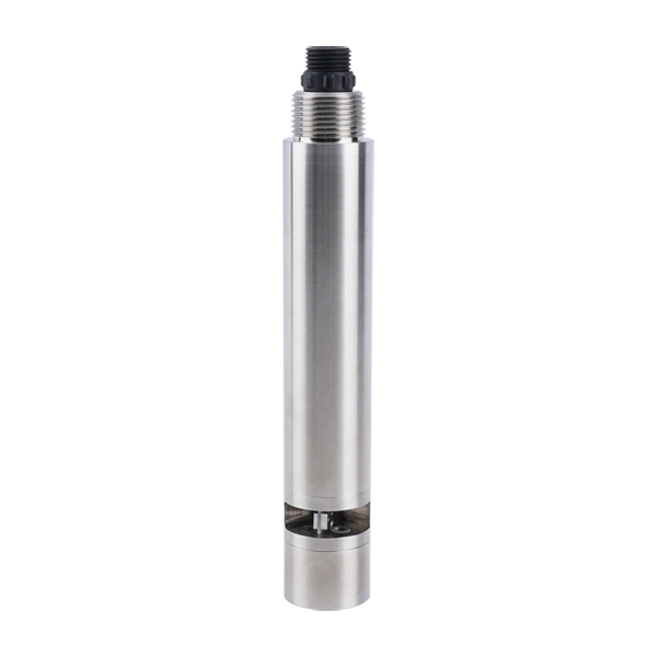
A slowly rising optical COD trend, a sudden step after cleaning and repeated communication failures need different investigations. Before retrieving the probe, save the recent trend with measurement times, treatment changes, rainfall or production events and the last successful reference comparison. Note whether the result is fresh or merely the last value retained by the logger.
For an immersed probe, record its depth and position. For a bypass installation, record actual sample flow and check that the line is receiving current process water. Settling in a long line can remove particles; a stagnant branch can delay a change. Neither problem is repaired by cleaning the optical window.
| Observed pattern | First check | Do not assume |
|---|---|---|
| Gradual offset between online and reference results | Window deposits, reference-sample timing and wastewater composition | Every offset requires a new calibration coefficient |
| Brief spikes near aeration or pumping | Bubbles, disturbed solids and probe movement | Every spike is a dissolved organic-load event |
| Reading changes after brush operation | Dislodged material, brush condition and recovery in representative water | The first post-cleaning value is ready for control |
| Timeouts or resets during cleaning | Voltage at the probe and the communication connection under load | Optical calibration can repair an electrical fault |
The NiuBoL NBL-WQ-COD-408-S uses dual-wavelength ultraviolet absorption and a cleaning brush. Its reference optical channel helps compensate for particle interference, but compensation does not remove all effects of deposits or changing wastewater chemistry. Keep the ordered range and model with the service record; do not transfer its cleaning load or temperature limit to another COD probe.
| COD-408-S item | Configuration | Maintenance consequence |
|---|---|---|
| COD ranges | 0-200, 0-500 or 0-1500 mg/L equivalent KHP | Use the actual ordered range and its applicable accuracy specification |
| Companion turbidity ranges | 0-200, 0-400 or 0-1000 NTU, respectively | Check particle events without assuming that turbidity alone validates COD |
| Cleaning | Self-cleaning brush | Inspect contact, wear and freedom of movement; a command alone does not demonstrate effective cleaning |
| Supply and power | 12-24 V DC; 0.4 W at 12 V measuring and 2 W cleaning | Check the field supply during brush operation, not only while idle |
| Interface | RS485 Modbus RTU; 4-20 mA optional | Confirm the delivered output before testing the receiving channel |
| Operating limits | 0-60 degrees C; pressure at or below 0.2 MPa; IP68 | Assess the actual sample and protect disconnected connectors separately |
| Construction | 316L stainless steel; standard 5 m cable | Inspect seals, cable strain and chemical exposure before redeployment |
KHP is potassium hydrogen phthalate, the calibration basis for the equivalent COD scale. A successful check on that scale verifies a defined optical response. It does not establish agreement with every digestion-based COD result in wastewater containing a different mixture of compounds.
When safe and operationally permitted, collect a reference sample at the sensing point before disturbing the probe. Record pH, temperature and other available process observations with it. A pH change can help identify a production or dosing event; it does not provide a numerical correction for COD. Keep each channel's purpose clear.
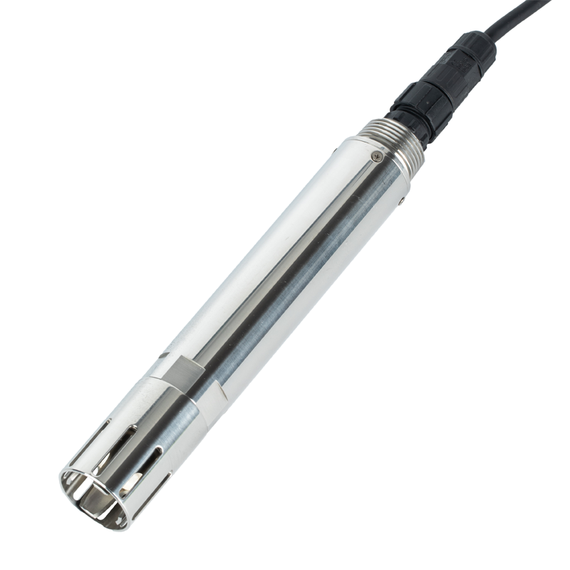
The pH sensor shown here is a separate supporting measurement, not a COD instrument. Its glass electrode and the COD probe's optical window require different handling. Use suitable retrieval equipment and the site's isolation procedure; do not carry the probe by its cable or start cleaning while an automatic control function interprets the service activity as process water.
Photograph deposits and inspect the optical path, guard, brush and cable before removing them. Note grease, biological growth, mineral deposits or trapped debris separately. If water ingress, a cracked window or a damaged connector is suspected, remove the affected assembly from service for assessment instead of attempting to compensate through calibration.
Use the model-approved cleaning method and a non-damaging contact material. Do not generalize an acid wash, solvent, abrasive pad or metal tool from another plant instrument. Clean the accessible housing and measuring area, rinse as required, then inspect for residual deposits and scratches. A visually clean housing does not prove that the optical path is clear.
For a brush-equipped unit, inspect the swept area and the brush itself. Check for missing or hardened bristles, wrapped fibers and obstruction. Isolate equipment appropriately before touching moving parts. After reassembly, test operation using the supported command and confirm that the brush actually moves through its intended path without striking a sensing surface.
A dissolved oxygen channel can help interpret a treatment change, but low DO does not quantify COD. Inspect and verify its optical cap independently. Cleaning one probe does not validate the other, even when both values enter the same PLC.
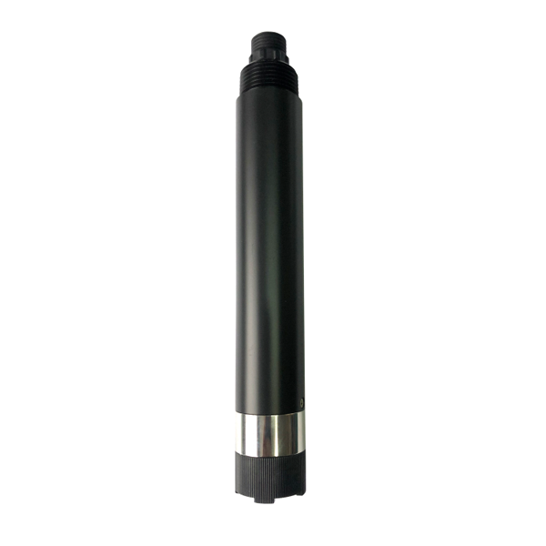
Return the COD probe to representative water and allow it to stabilize under the model's procedure and actual site conditions. Compare the cleaned result with the arrival reading and a suitable reference. Water may change during the visit, so do not attribute the entire difference between two measurements an hour apart to fouling.
If the sensor behaves correctly in suitable standards but disagrees with laboratory COD in the sample, investigate the correlation, sample treatment and wastewater composition. Collect paired samples over the relevant operating conditions. A coefficient fitted to yesterday's process water may not describe a new dye, feedstock or chemical treatment.
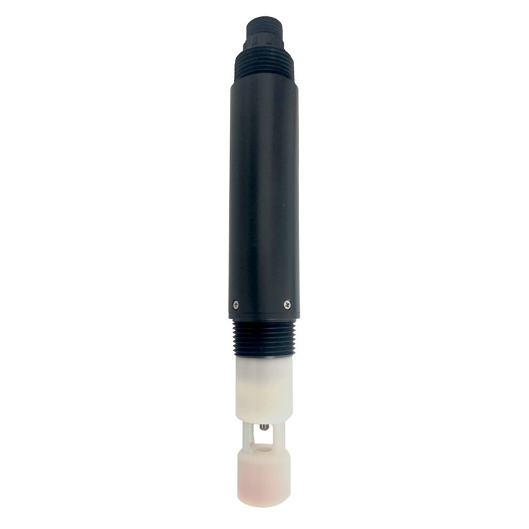
Conductivity is useful here as evidence of an ionic-background change, not as a universal conversion to organic load. The conductivity/salinity sensor illustrated below has its own calibration and temperature-reporting basis. Preserve those settings when comparing it with the COD trend.
When calibration is justified, retain the as-found results, standard identity, temperature, adjustment and independent post-adjustment check. Keep calibration writes separate from routine Modbus reads. Use the exact instrument's register definition and supported procedure; do not copy addresses or hexadecimal commands from another NiuBoL model.
Begin with the selected instrument's service requirements and a conservative inspection plan appropriate to access and fouling. Compare arrival checks across successive visits. If cleaned performance is satisfactory but the as-found disagreement grows before each visit, shorten the interval or improve the location and cleaning arrangement. Repeatedly recalibrating a coated window hides that pattern.
A treated-effluent point and a grease-rich equalization tank need not share the same schedule. Include safe retrieval time, brush or seal service, reference analysis and the period without valid measurements. Where outage matters, assess a compatible spare rather than assuming that an unattended brush removes the need for field service.
An optical BOD sensor is another organic-related channel, but it is not a spare COD probe and does not perform a five-day incubation test. Its fluorescence response needs a separate application relationship and service record. Shared units or an RS485 connection do not make the analytical methods interchangeable.

No. Deposits can remain outside the swept area, a brush can wear, and sampling or electrical faults can persist. Establish the useful interval from field checks and service requirements rather than from the presence of a brush.
Not automatically. Inspect, clean and verify first. Adjust when the supported procedure and reference checks establish a need. Preserve both the original result and the result after adjustment.
Online optical estimates and digestion methods respond differently to sample composition. Also check sampling time, particles, dilution and sample handling. A clean optical path does not establish a universal wastewater correlation.
Measure supply at the instrument during the event and inspect the feed and connections. COD-408-S lists 2 W during cleaning versus 0.4 W during measurement at 12 V. Include other shared loads; a cabinet-side voltage reading alone can miss a field-end drop.
Send NiuBoL the model, version, ordered range, fault history, inspection photos and reference results. Identify whether the problem concerns the brush, seals, cable or optical assembly. Confirm the permitted replacement procedure before ordering a part or opening a sealed body.
Verify representative immersion or sample delivery, stable measurement, suitable reference agreement and matching units in the PLC or data logger. Confirm that maintenance status has ended and the last service reading is not being presented as current process data.
A separate turbidity probe can help investigate particle-related changes, but it cannot determine the COD correction by itself. Verify its own window, clearances and range. Keep that distinction when reviewing whether a post-maintenance step belongs to the water, the optical response or the receiving software.
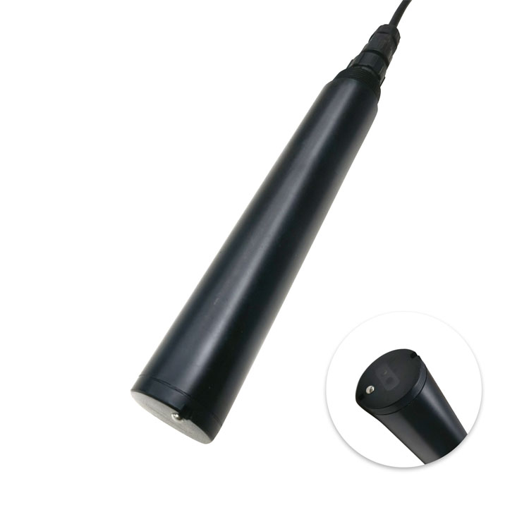
Useful COD sensor maintenance preserves the evidence before intervention and checks what each intervention changed. Separate deposits from electrical faults and wastewater-composition changes, verify the cleaned probe before adjusting it, and derive service intervals from field performance. For a maintenance quotation, provide the exact model and recorded fault so the proposed parts and work address the actual cause.
Prev:Insect Monitoring System: Which Species Can a Trap Identify?
Next:Online Water Quality Sensor Care During Pond Draining and Refilling
Related recommendations
Sensors & Weather Stations Catalog
 Agriculture Sensors and Weather Stations Catalog-NiuBoL.pdf
Weather Stations Catalog-NiuBoL.pdf
Agriculture Sensors Catalog-NiuBoL.pdf
Water Quality Sensor Catalog-NiuBoL.pdf
Related products
 Combined air temperature and relative humidity sensor
 TDR Soil Moisture & Temperature Sensor for irrigation| RS485 |4-20mA| NBL-S-THR
 Soil pH sensor RS485 soil Testing instrument soil ph meter for agriculture |NBL-S-PH
 Wind Speed sensor Output Modbus/RS485/Analog/0-5V/4-20mA
 Tipping bucket rain gauge for weather monitoring auto rainfall sensor RS485/Outdoor/stainless steel
 Pyranometer Solar Radiation Sensor 4-20mA/RS485


Screenshot, WhatsApp to identify the QR code
WhatsApp number:+8615367865107
(Click on WhatsApp to copy and add friends)

