





— Blogs —
—Products—
 Consumer hotline +8618073152920
WhatsApp:+8615367865107
Address:Room 102, District D, Houhu Industrial Park, Yuelu District, Changsha City, Hunan Province, China
Product knowledge
Time:2024-10-06 14:20:14 Popularity:1963
An automatic weather observation station can collect and transmit readings without an observer recording each one, but it still needs physical inspection and servicing. Plan access to collectors, sensing surfaces, connectors and the enclosure before installation. A compact layout is not useful if routine work requires disturbing other measurements.
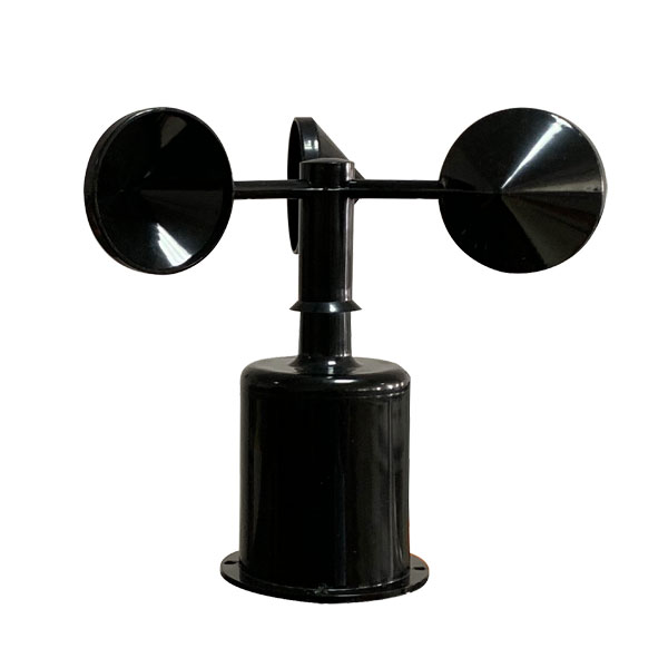
A cup anemometer needs clearance for rotation and a practical way to inspect the rotor without leaning on the sensing assembly. Do not use the cups as a lifting or handhold point. For the NBL-W-SS, specify IP65 and check the ordered connection; neither item defines a safe access method for an elevated installation.
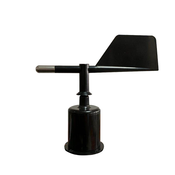
A wind vane needs an orientation mark that remains usable after removal. Record its north reference and bracket position so a replacement can be aligned deliberately rather than approximately. For NBL-W-DS, use IP65. Leave room for the vane to move through its full travel without contact with cables or nearby instruments.
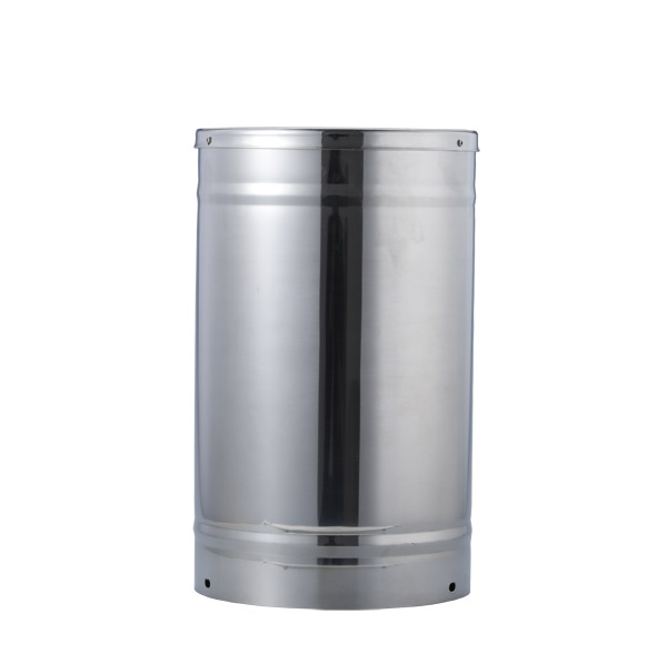
A stainless steel tipping-bucket rain gauge needs access above the collector and to the internal mechanism. A bracket that permits installation but prevents opening the housing creates recurring difficulty. Keep the collector's exposure separate from the technician's working space; a permanent platform or handrail must not obstruct rain entering the gauge.
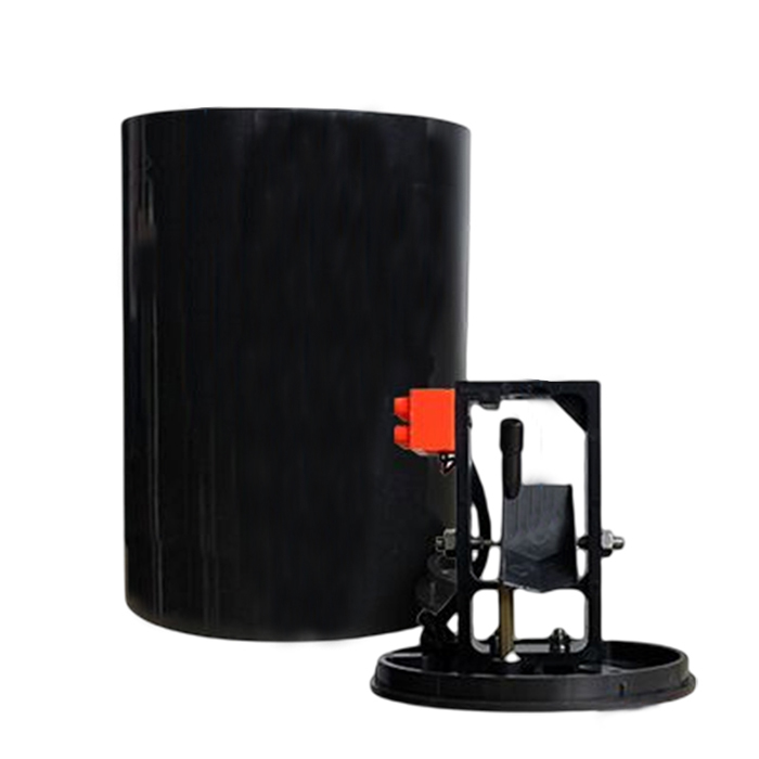
An ABS tipping-bucket gauge also needs its funnel and bucket mechanism to be accessible. Check how the actual housing opens before setting bracket spacing. Provide a way to observe the mechanism during an authorized functional check without pulling on the signal cable or changing the level of the installed gauge.
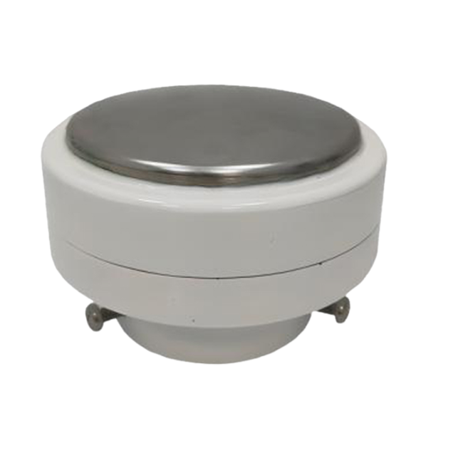
A piezoelectric precipitation head has no collection bucket to empty, but its exposed impact surface still requires inspection. Keep adjacent brackets and cables from contacting the sensing head. Maintenance access should not introduce a vibrating platform into the installation, and cleaning procedures must match the selected instrument rather than a bucket-gauge routine.
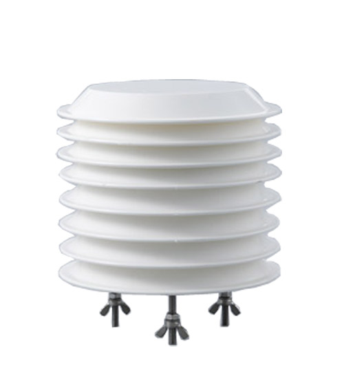
A louvered temperature, humidity and pressure assembly needs open airflow through its shield. Position it so inspection does not require removing neighboring solar or wind instruments. An enclosure may protect electronics, but placing the atmospheric sensing assembly inside a sealed cabinet would change what it measures rather than improve its weather protection.
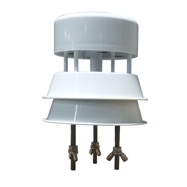
For an ultrasonic wind instrument, preserve the acoustic paths and access to the mounting connection. The transducer supports are measurement geometry, not convenient handles. A technician should be able to inspect the head without bending these parts or temporarily hanging cables across the paths used for wind measurement.
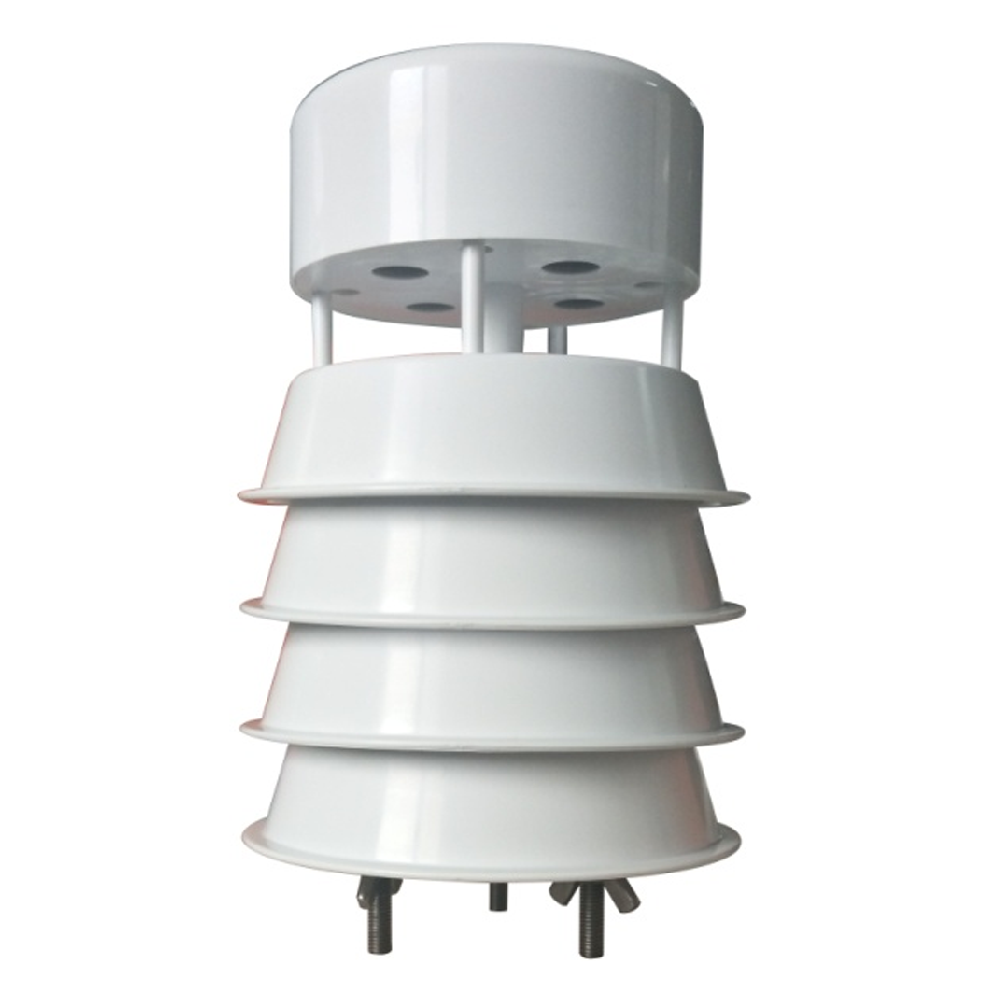
A five-parameter integrated head concentrates several channels in one assembly. The maintenance drawing should show how that head is disconnected and removed, including cable slack and fastener access. Count the channels that will become unavailable during removal so the operator understands the scope of a service interruption.
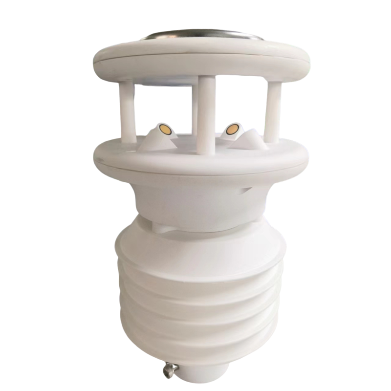
An all-in-one weather assembly may simplify initial wiring while requiring access around a larger sensing head. Leave space for the unit to be withdrawn along its intended mounting direction. A narrow gap between the head and mast can make a connector reachable during assembly but inaccessible after the structure is erected.
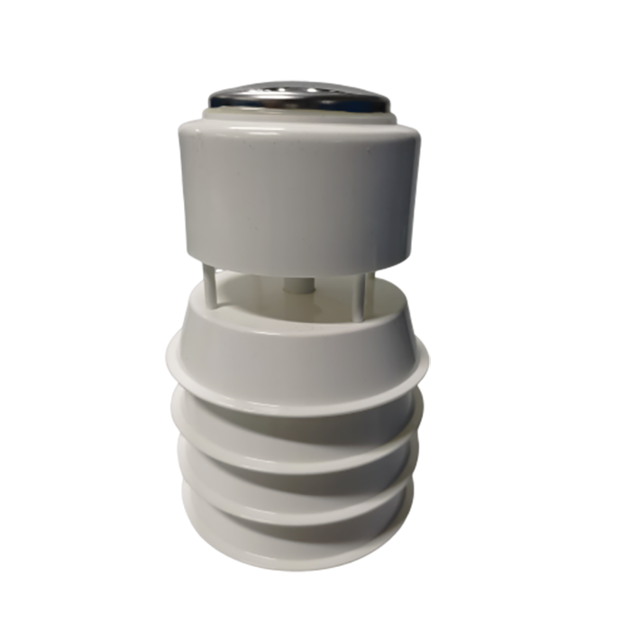
A seven-parameter weather head can include sensing areas with different inspection needs. Confirm their locations on the ordered model before positioning the bracket. Access to one surface must not depend on touching another delicate component. If the whole head must be removed, plan how its original alignment will be recovered.

A flat solar radiation detector needs an unobstructed measurement plane and access to its sensing window. A worker's temporary position during cleaning is not the permanent exposure, but a new service rail or cable loop is. Inspect the completed layout from the detector's position before accepting the installation.
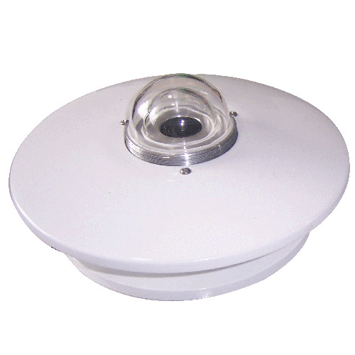
A domed pyranometer needs room to inspect and clean its optical surface using the product's approved procedure. Avoid an arrangement that requires loosening the levelling base for every cleaning visit. After work involving the mounting, recheck level and orientation rather than assuming the previously recorded installation remains unchanged.
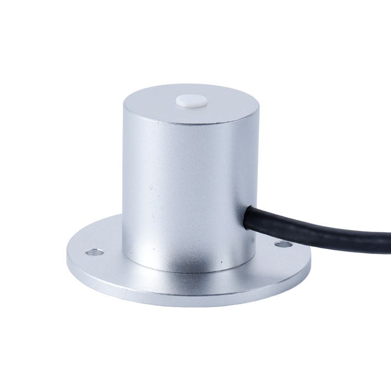
A PAR sensor may be mounted near crops or on a structure that changes during a growing season. Plan access without repeatedly compressing the surrounding plants or moving the detector. Document its measurement plane so a later adjustment for convenience is not mistaken for an unchanged plant-light observation.
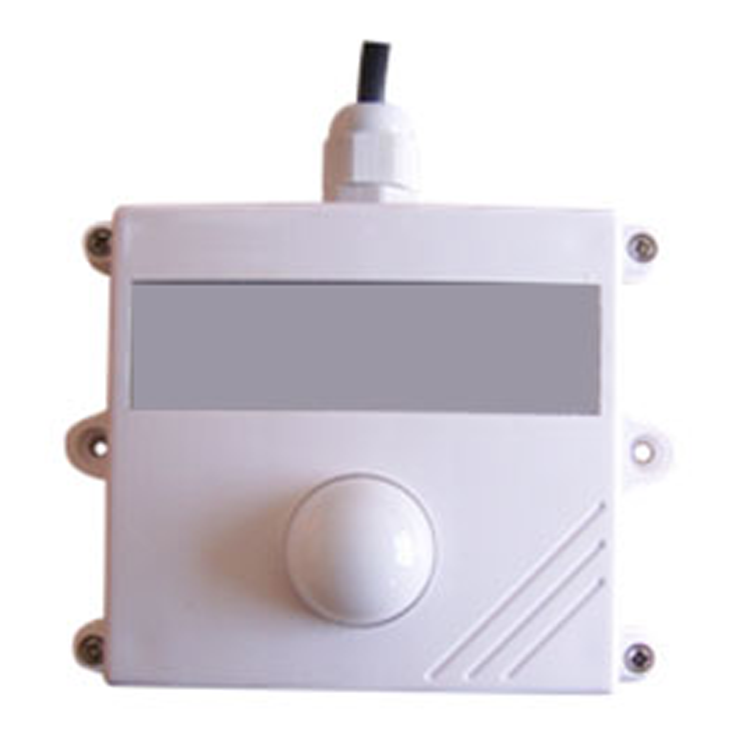
An illuminance sensor needs an exposed optical surface, but its access requirements depend on the actual mounting style. Keep nearby labels, cable ties and replacement brackets outside the intended view. Cleaning the window does not authorize moving the instrument to a shaded face of the mast simply because it is easier to reach.

A downward-looking snow depth sensor needs a stable reference patch as well as access to the head. Do not place the routine walking route directly beneath it. Footprints, cleared snow or a service platform can change the reflecting surface, so plan the winter approach route before the first accumulation occurs.
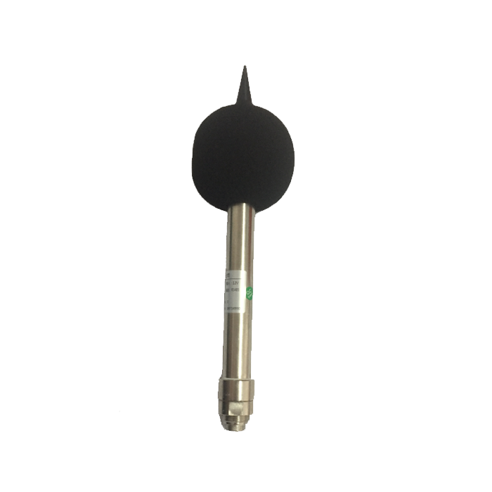
A noise sensor may use a microphone windscreen that needs inspection or replacement. Allow access without repositioning the microphone or adding a nearby reflecting panel. The station layout should distinguish an acoustic observation point from a general equipment mounting location; convenient access alone does not make the position acoustically representative.
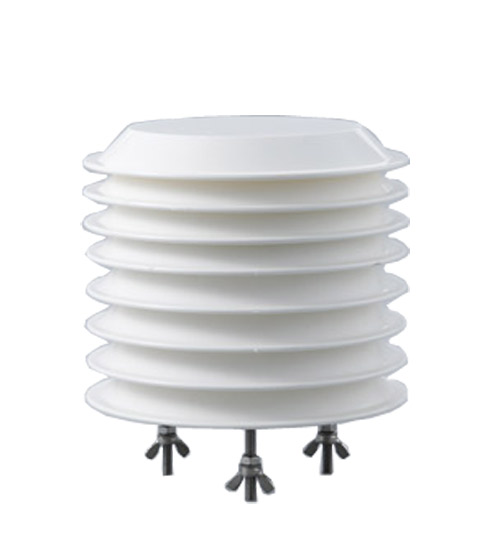
A CO2 assembly needs its sampling openings exposed to the intended air. Leave access to inspect vents and any model-specific service parts without opening unrelated equipment. Avoid locating the working position so a technician's breath becomes the main sample during a check; allow readings to recover before interpreting the result.
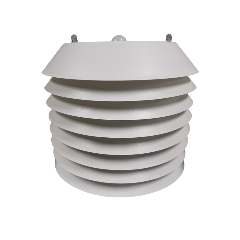
A particulate sensor requires attention to its inlet and, where present on the selected model, its air path and service components. Leave the withdrawal space shown by the product arrangement. Do not assume that wiping the outside of a radiation shield is the complete maintenance procedure for an internal particle measurement module.

A visibility sensor has optical heads whose alignment and viewing space must remain intact. Provide access to each optical surface rather than only to the mounting bolts. A technician should not need to brace against an opposing optical arm. Permanent access equipment must also remain outside the instrument's intended measurement region.
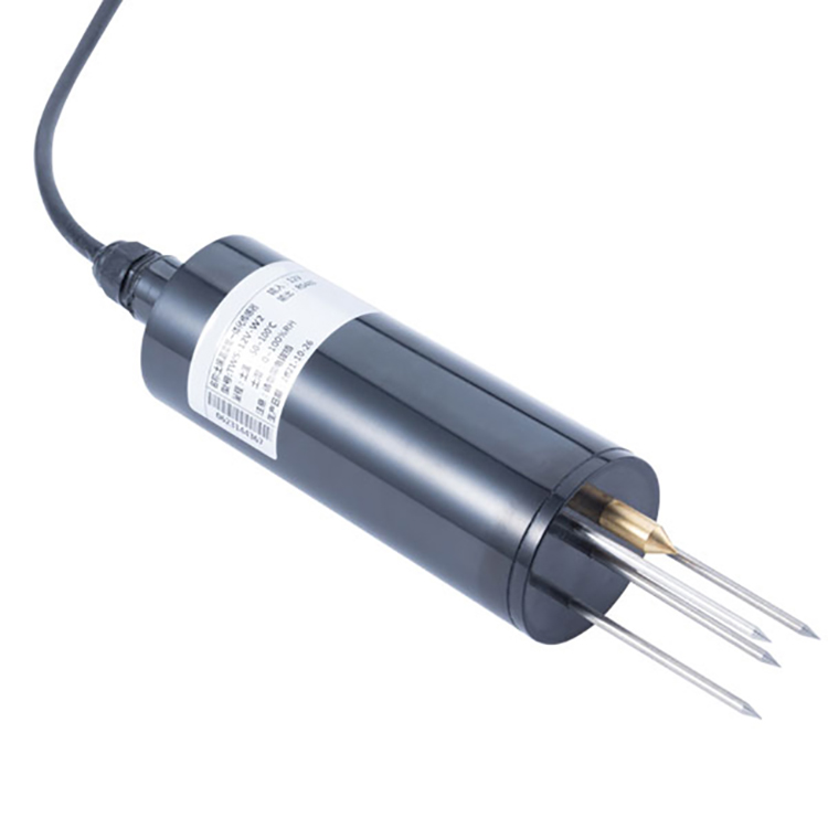
A buried soil probe introduces a different service problem: reaching it can disturb the measurement volume. Mark the installation depth and cable route, and provide strain relief above ground. If removal is necessary, record the reinstallation; the resulting record should not imply that an undisturbed soil observation continued throughout the work.
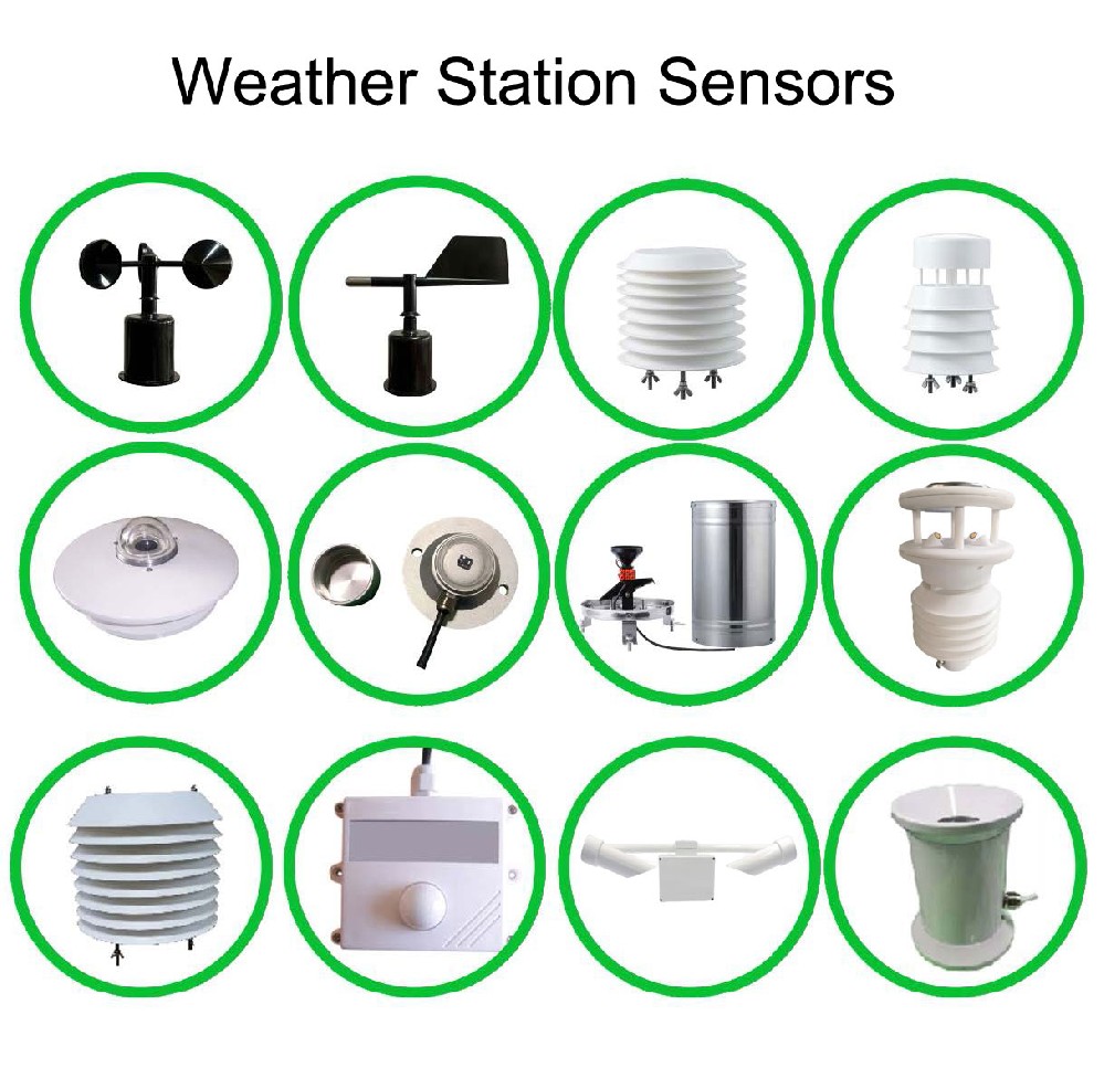
The automatic weather observation station drawing should show more than the footprint of each sensor. Include cover-opening space, connector withdrawal, cable bends and the worker's approach. Distinguish tasks that can be performed from ground level from those requiring a planned elevated-access method. A mast photograph alone cannot establish that the arrangement is serviceable.
| Item to check | Practical test before erection | What to record |
|---|---|---|
| Rain collector | Open the housing and reach the mechanism without moving the mounting. | Opening clearance and collector levelling method. |
| Integrated weather head | Disconnect and remove the assembly using its intended fastening points. | Channels interrupted and alignment reference. |
| Radiation detector | Reach the optical surface without loosening its base. | Measurement plane and post-service level check. |
| Enclosure | Open the door fully and reach terminals with the intended tools. | Working clearance and cable entry arrangement. |
| Soil cable | Trace the above-ground route without pulling the buried probe. | Probe position, depth and strain-relief point. |
| Snow reference patch | Identify an access route that does not cross the observed patch. | Reference location and winter approach route. |
There is no universal clearance dimension for all these instruments. Use the actual selected head, enclosure and mounting hardware in the check. If a supplier drawing does not show the opening or removal path, request it before fabrication rather than assuming a nominal sensor diameter defines the required service space.
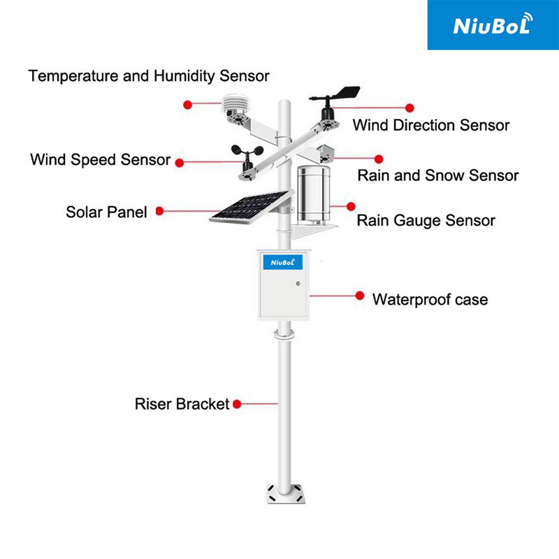
Keep the data logger, RTU and communications terminals accessible without disturbing sensor exposure. Provide cable slack for the enclosure door and for removing a module, while supporting cables so their weight does not load terminals. Label connections at both ends; an unlabeled cable bundle makes a simple sensor check unnecessarily disruptive.
RS485 and Modbus RTU compatibility still require the correct ordered devices and configuration. Separately identify analog, pulse and relay wiring. Any isolation or disconnection procedure must be designed for the actual circuit by qualified personnel; unplugging a powered shared connection can affect more than the instrument being serviced.

A remote display can show that a value has stopped updating, but it may not reveal a blocked rain funnel, a dirty optical surface or a shifted soil probe. Define which conditions have an actual device diagnostic and which require a visit. Do not describe a station as self-maintaining because it uploads data automatically.
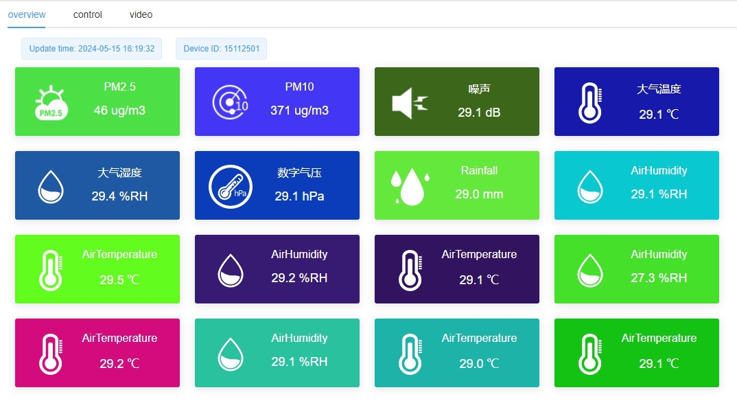
At commissioning, match displayed channel names with labels at the instruments and enclosure. Record the observation time separately from any maintenance note. The illustrated display is only one arrangement; the project's software functions, access permissions and diagnostic fields need to be specified rather than inferred from a screenshot.
In a cultivated field, access must account for crop growth, machinery routes and wet ground. A path available during installation may disappear later. Protect cable routes from the planned cultivation work, and avoid making a rain collector accessible only by stepping into an area whose soil conditions are being monitored.
In an industrial or roadside installation, coordinate the weather station's service position with site access rules and traffic or equipment movement. If work near the mast requires isolation or a permit, include that constraint in the design discussion. Do not promise a particular response time without considering the site's entry restrictions.
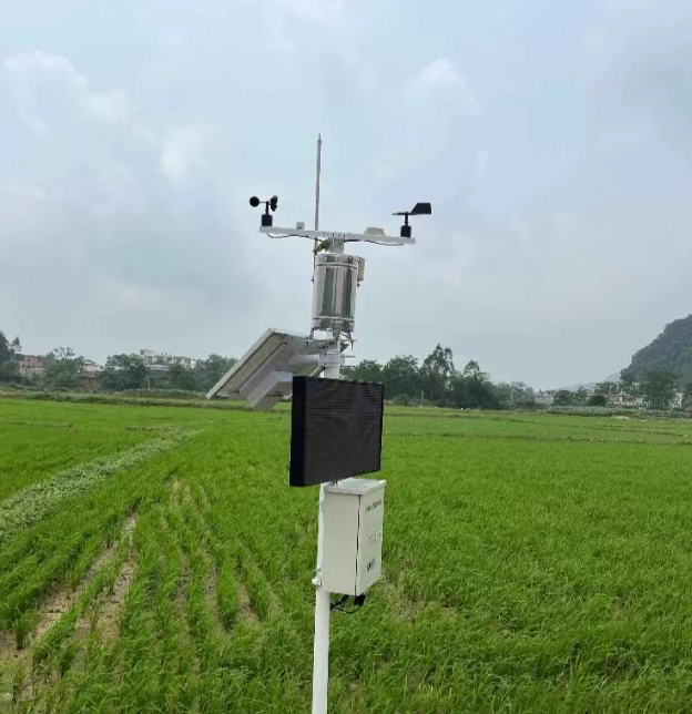
A compact environmental mast can become difficult to service as instruments are added. Before accepting an extension, repeat the access check with the new bracket shown in place. A technically compatible sensor can still create a poor installation by blocking another instrument's cover, optical path or removal direction.
For remote stations, decide which work can realistically be performed during one visit and which parts must be removed for workshop service. Keep the relevant equipment identification available offline. Solar power does not eliminate visits: panel condition, battery care and electrical inspection depend on the selected system and local conditions.
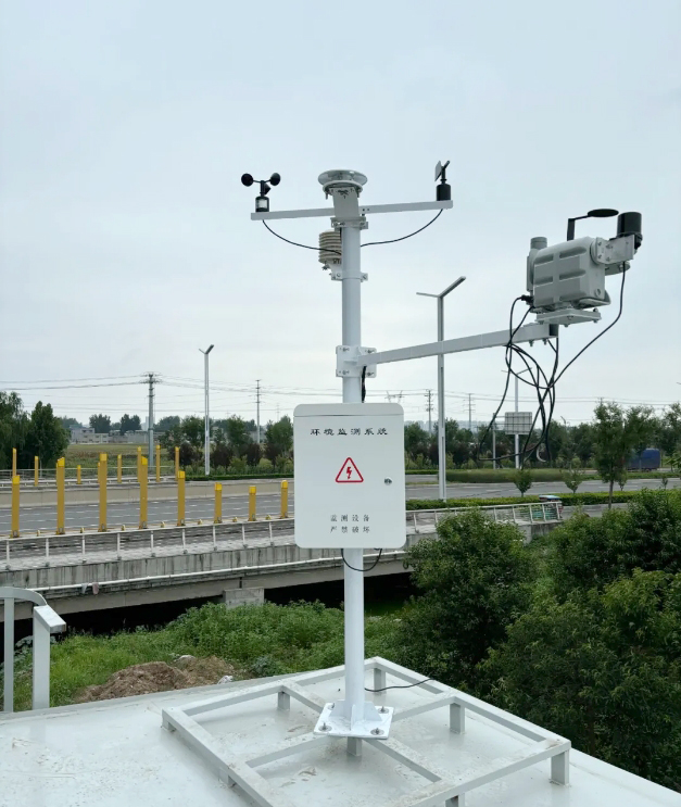
Vegetation and nearby structures can change access and exposure after installation. Look around the complete automatic weather observation station rather than only at the instrument listed on the work order. Record new obstructions and any changes made during the visit; do not silently trim or move site features outside the agreed work scope.
For detailed fault diagnosis, use a separate weather station maintenance procedure suited to the equipment. Access planning answers whether the work can be performed without disturbing other observations. It does not replace calibration instructions, electrical safety procedures or the manufacturer's model-specific servicing limits.
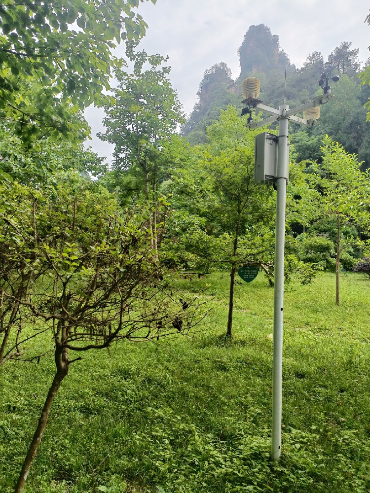
Not necessarily. The answer depends on instrument height, task and the approved access method. Ground-accessible instruments and an elevated weather head may need different arrangements. Select access equipment through the site safety process, and make sure permanent platforms do not compromise rainfall, wind or radiation exposure.
Only if the supplied structure is designed and approved for that operation. Do not improvise a tilting arrangement on a fixed mast. If lowering is part of the maintenance concept, assess cable movement, personnel clearance, alignment recovery and which channels must be taken out of service.
No. Collection funnels, optical windows, microphone accessories and buried probes have different inspection needs. Establish the first inspection intervals from the selected equipment and site exposure, then review actual contamination and performance. A fixed universal interval can create unnecessary disturbance at one sensor while overlooking another.
No. Confirm that an authorized worker can open the enclosure, reach service parts and remove the selected instruments without shifting neighboring measurements. Remote access can demonstrate data reception, not physical access. Both should be checked before the installation team leaves the site.
Provide the sensor list, intended heights, site photographs and access restrictions. Ask for the proposed bracket and enclosure arrangement and identify expected service tasks. This allows mounting and cable requirements to be reviewed before manufacture rather than leaving access problems to the installer.
Check the features disturbed by the work: wind direction reference, radiation sensor level, collector level, snow reference geometry or soil probe position as applicable. Then verify the affected channel at the receiver. Record the service period so the data user can distinguish interrupted observations from valid measurements.
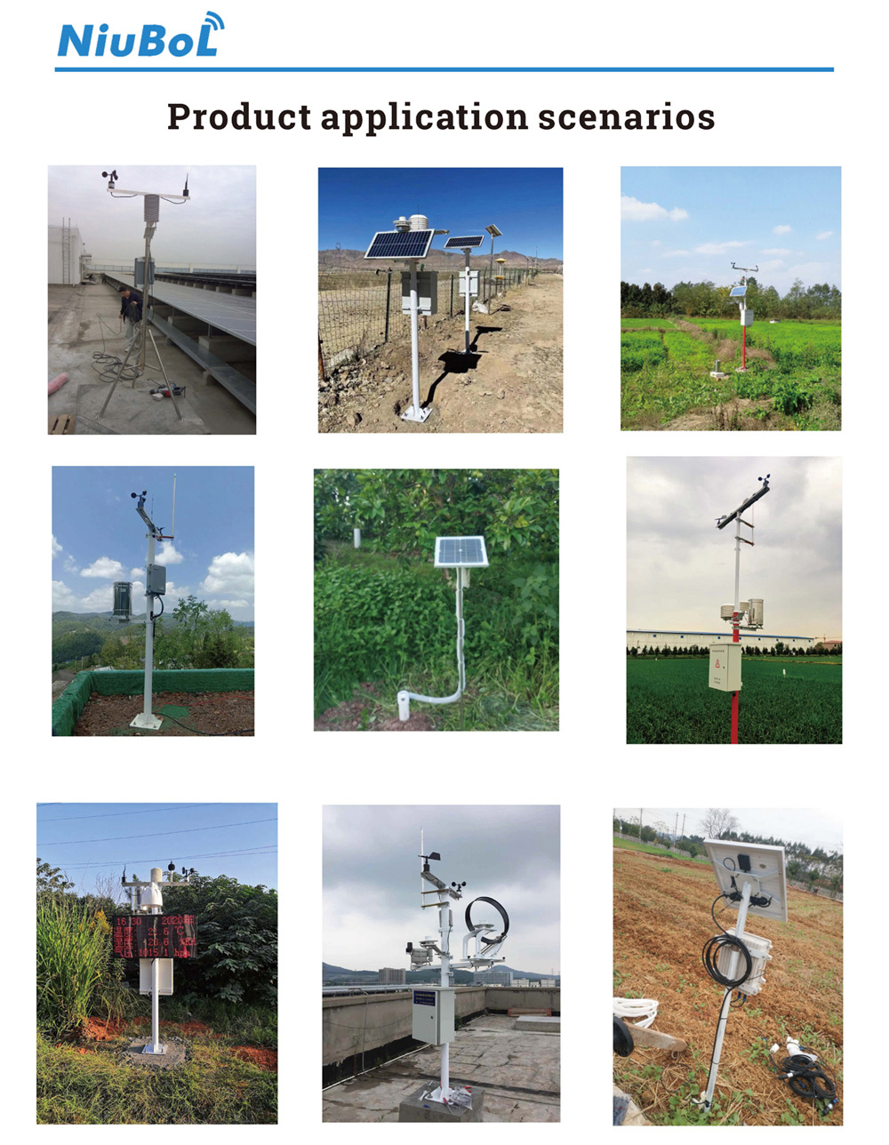
An automatic weather observation station should be designed for the work it will need after installation. NiuBoL sensor selection and system assembly should be reviewed alongside cover clearances, removal routes and safe access. Preserving exposure during routine service is part of preserving the usefulness of the observation record.
Prev:Weather Station Power Supply: When Solar or Mains Makes Sense
Next:What Is a Snow Sensor? Presence, Depth and Water Equivalent
Related recommendations
Sensors & Weather Stations Catalog
 Agriculture Sensors and Weather Stations Catalog-NiuBoL.pdf
Weather Stations Catalog-NiuBoL.pdf
Agriculture Sensors Catalog-NiuBoL.pdf
Water Quality Sensor Catalog-NiuBoL.pdf
Related products
 Combined air temperature and relative humidity sensor
 TDR Soil Moisture & Temperature Sensor for irrigation| RS485 |4-20mA| NBL-S-THR
 Soil pH sensor RS485 soil Testing instrument soil ph meter for agriculture |NBL-S-PH
 Wind Speed sensor Output Modbus/RS485/Analog/0-5V/4-20mA
 Tipping bucket rain gauge for weather monitoring auto rainfall sensor RS485/Outdoor/stainless steel
 Pyranometer Solar Radiation Sensor 4-20mA/RS485


Screenshot, WhatsApp to identify the QR code
WhatsApp number:+8615367865107
(Click on WhatsApp to copy and add friends)

